|
|

Table Of Contents
Configuring a Public Network Tunnel Interface
Configuring Signaling VPCI for PVP Tunnels
Configuring a PVC to a VP Tunnel
Configuring a VPI or VCI Range for SVPs or SVCs
Configuring ATM Interfaces
This chapter describes how to explicitly configure ATM network interface types. Explicitly configuring interfaces is the alternative to Interim Local Management Interface (ILMI) autoconfiguration, which senses the peer interface type and appropriately configures the Cisco 6000 family DSLAM interface.
Use the network configuration tasks described in this chapter to explicitly change your ATM DSLAM operation from the defaults, which are suitable for most networks. This chapter includes these sections:
•
Network Configuration Example
•
•
•
Network Configuration Example
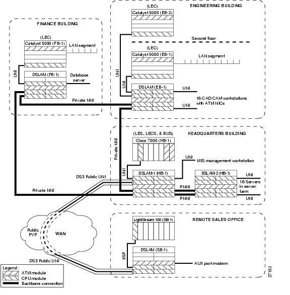
The sample network shown in Figure 8-1 illustrates some standard ATM interface configuration tasks you can perform after you complete the initial DSLAM configuration. See Chapter 3, "Initially Configuring the Cisco DSLAM."
Figure 8-1 Sample Network Configuration
The network configuration shown in Figure 8-1 is an example of a corporate campus ATM backbone network connecting three buildings with an ATM connection across the WAN to a remote sales office.
The remaining sections in this chapter describe a possible configuration of the network that appears in Figure 8-1.
Disabling Autoconfiguration
When an interface comes up initially, autoconfiguration determines the type of interface. To configure the interface protocol on an interface, you must first disable the autoconfiguration feature.
To disable autoconfiguration on an interface, perform these steps, beginning in global configuration mode:
1.
interface atm slot/port[.vpt#]
Select the interface to be configured.
2.
no atm auto-configuration
Disable autoconfiguration on the interface.
Example
In this example, autoconfiguration is disabled on interface ATM 0/1 and the results are as follows:
DSLAM(config)# interface atm 0/1DSLAM(config-if)# no atm auto-configurationDSLAM(config-if)#%ATM-6-ILMINOAUTOCFG: ILMI(ATM0/1): Auto-configuration is disabled, current interface parameters will be used at next interface restart.DSLAM# atm interface atm 0/1Interface: ATM0/1 Port-type: suni_dualIF Status: UP Admin Status: upAuto-config: disabled AutoCfgState: not applicableIF-Side: Network IF-type: NNIUni-type: not applicable Uni-version: not applicableMax-VPI-bits: 8 Max-VCI-bits: 14Max-VP: 255 Max-VC: 16383Svc Upc Intent: pass Signalling: EnabledATM Address for Soft VC: 47.0091.8100.0000.0040.0b0a.2b81.4000.0c80.8000.00Configured virtual links:PVCLs SoftVCLs SVCLs PVPLs SoftVPLs SVPLs Total-Cfgd Installed-Conns3 0 0 0 0 0 3 3Logical ports(VP-tunnels): 0Input cells: 234663 Output cells: 2354835 minute input rate: 0 bits/sec, 0 cells/sec5 minute output rate: 0 bits/sec, 0 cells/secInput AAL5 pkts: 153211, Output AAL5 pkts: 153626, AAL5 crc errors: 0Configuring UNI Interfaces
The UNI specification defines communications between ATM end stations (such as workstations and routers) and ATM switches in private ATM networks. (The DSLAM functions as an ATM switch.)
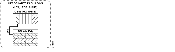
To configure a UNI interface between the DSLAM (HB-1) in the headquarters building to the Cisco 7000 (HB-1) in the same building, use the atm uni command in interface configuration mode. Figure 8-2 shows a detail of this type of network connection.
Figure 8-2 Multiple Link UNI Example
To configure the UNI interface, perform these steps, beginning in global configuration mode:
Note
Example
This example disables autoconfiguration on ATM interface 0/1 and to configure the interface as the user side of a private UNI running Version 4.0:
DSLAM(HB-1)(config)# interface atm 0/1DSLAM(HB-1)(config-if)# no atm auto-configurationDSLAM(HB-1)(config-if)#%ATM-6-ILMINOAUTOCFG: ILMI(ATM0/1): Auto-configuration is disabled, current interface parameters will be used at next interface restart.DSLAM(HB-1)(config-if)# atm uni side user type private version 4.0DSLAM(HB-1)(config-if)#%ATM-5-ATMSOFTSTART: Restarting ATM signalling and ILMI on ATM0/1.To show the ATM interface UNI configuration, use this EXEC command:
Example
This example displays the ATM interface 0/1 UNI configuration:
DSLAM(HB-1)# show atm interface atm 0/1Interface: ATM0/1 Port-type: suni_dualIF Status: UP Admin Status: upAuto-config: disabled AutoCfgState: not applicableIF-Side: User IF-type: UNIUni-type: Private Uni-version: V4.0Max-VPI-bits: 8 Max-VCI-bits: 14Max-VP: 255 Max-VC: 16383Svc Upc Intent: pass Signalling: EnabledATM Address for Soft VC: 47.0091.8100.0000.0040.0b0a.2b81.4000.0c80.8000.00Configured virtual links:PVCLs SoftVCLs SVCLs PVPLs SoftVPLs SVPLs Total-Cfgd Installed-Conns2 0 0 0 0 0 2 2Logical ports(VP-tunnels): 0Input cells: 234810 Output cells: 2356185 minute input rate: 0 bits/sec, 0 cells/sec5 minute output rate: 0 bits/sec, 0 cells/secInput AAL5 pkts: 153296, Output AAL5 pkts: 153712, AAL5 crc errors: 0Configuring NNI Interfaces
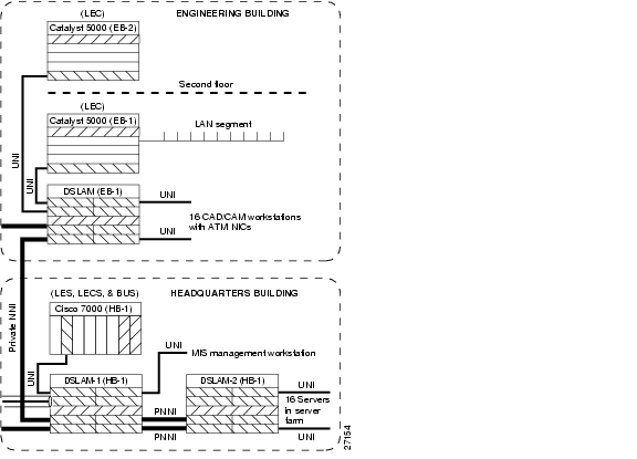
This section describes the configuring of a Network-to-Network Interface (NNI) connection between two switches. The example in this section involves the configuring of a Private NNI (PNNI) interface from the DSLAM (HB-1) in the headquarters building to the DSLAM (EB-1) in the Engineering building, as shown in Figure 8-3.
Figure 8-3 Private NNI Interface Example
You must configure PNNI connections between the ATM switches to allow for route discovery and topology analysis between the switches. To configure the NNI interface, perform these steps, beginning in global configuration mode:
Note
Example
This example configures ATM interface 0/1 on the DSLAM located in the headquarters building as an NNI interface and displays the results:
DSLAM(HB-1)(config)# interface atm 0/1DSLAM(HB-1)(config-if)# no atm auto-configurationDSLAM(HB-1)(config-if)#%ATM-6-ILMINOAUTOCFG: ILMI(ATM0/1): Auto-configuration is disabled, current interface parameters will be used at next interface restart.DSLAM(HB-1)(config-if)# atm nniDSLAM(HB-1)(config-if)#%ATM-5-ATMSOFTSTART: Restarting ATM signalling and ILMI on ATM0/1.DSLAM(HB-1)# show atm interface atm 0/1Interface: ATM0/1 Port-type: suni_dualIF Status: UP Admin Status: upAuto-config: disabled AutoCfgState: not applicableIF-Side: Network IF-type: NNIUni-type: not applicable Uni-version: not applicableMax-VPI-bits: 8 Max-VCI-bits: 14Max-VP: 255 Max-VC: 16383Svc Upc Intent: pass Signalling: EnabledATM Address for Soft VC: 47.0091.8100.0000.0040.0b0a.2b81.4000.0c80.8000.00Configured virtual links:PVCLs SoftVCLs SVCLs PVPLs SoftVPLs SVPLs Total-Cfgd Installed-Conns3 0 0 0 0 0 3 3Logical ports(VP-tunnels): 0Input cells: 234911 Output cells: 2356955 minute input rate: 0 bits/sec, 0 cells/sec5 minute output rate: 0 bits/sec, 0 cells/secInput AAL5 pkts: 153346, Output AAL5 pkts: 153764, AAL5 crc errors: 0Configuring IISP Interfaces
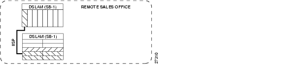
This section describes how to configure the Interim Interswitch Signaling Protocol (IISP) interface from the DSLAM (SB-1) in the Remote Sales building to the DSLAM (SB-1) in the same building. Figure 8-4 shows an example of this type of network configuration.
Figure 8-4 IISP Network Segment Example
Some ATM switches do not support the Private Network-to-Network Interface (PNNI) protocol. Switched virtual circuit (SVC) support can be provided by configuring the interface to use IISP.
To configure the IISP interfaces in Figure 8-4, perform these tasks, beginning in global configuration mode:
Note
Example
This example configures ATM interface 0/1 on the DSLAM (SB-1) located in the Remote Sales building with these parameters, and displays the results:
•
•
•
•
DSLAM(SB-1)(config)# interface atm 0/1DSLAM(SB-1)(config-if)# no atm auto-configurationDSLAM(SB-1)(config-if)#%ATM-6-ILMINOAUTOCFG: ILMI(ATM0/1): Auto-configuration is disabled, current interface parameters will be used at next interface restart.DSLAM(SB-1)(config-if)# atm iisp side userDSLAM(SB-1)(config-if)#%ATM-5-ATMSOFTSTART: Restarting ATM signalling and ILMI on ATM0/1.DSLAM(SB-1)(config-if)# exitDSLAM(SB-1)(config)# atm route 47.0091.8100.0000.0000.0ca7.ce01 atm 0/1DSLAM(SB-1)(config)# show atm int 0/1Interface: ATM0/1 Port-type: suni_dualIF Status: DOWN Admin Status: downAuto-config: disabled AutoCfgState: not applicableIF-Side: User IF-type: IISPUni-type: not applicable Uni-version: V3.0Max-VPI-bits: 8 Max-VCI-bits: 14Max-VP: 255 Max-VC: 16383Svc Upc Intent: pass Signalling: EnabledATM Address for Soft VC: 47.0091.8100.0000.0040.0b0a.2b81.4000.0c81.8000.00Configured virtual links:PVCLs SoftVCLs SVCLs PVPLs SoftVPLs SVPLs Total-Cfgd Installed-Conns2 0 0 0 0 0 2 0Logical ports(VP-tunnels): 0Input cells: 0 Output cells: 05 minute input rate: 0 bits/sec, 0 cells/sec5 minute output rate: 0 bits/sec, 0 cells/secInput AAL5 pkts: 0, Output AAL5 pkts: 0, AAL5 crc errors: 0Configuring a Public Network Tunnel Interface
This section describes how to configure the DS3 public UNI ATM connection as a virtual path (VP) tunnel from the headquarters building across the WAN to the Remote Sales building.
Note
Figure 8-5 shows a detail of the sample network you are configuring.
Figure 8-5 Public VP Tunnel Network Example
Public DS3 carriers can interconnect switches using permanent VPs across their networks. To support signaling across the public network between the DSLAM (HB-1) in the headquarters building and the Remote Sales building the DSLAM (SB-1), you must configure a VP tunnel.
Assigning VPI Values to Shaped VP Tunnels
If you configure VP tunnels with traffic shaping, you can use only 32 VPIs, even though the full range of VPI values is 0 to 255. If you have not yet assigned any VPIs, all values from 0 to 255 are available. Once you start assigning VPIs, however, the assigned VPIs limit the VPIs that remain. (You assign VPIs using the atm pvp or atm pvc commands.)
After a particular VPI value is assigned to a shaped VP tunnel, every 32nd VPI value above and below the first one is eliminated—that is, the original value modulo 32. For example, if you assign VPI 94 to a shaped VP tunnel, the following VPI values become unavailable for any purpose: 30, 62, 126, 158, 190, and 222.
To avoid problems, choose a block of 32 consecutive VPI values (for example, 0 to 31 or 101 to 132). The software rejects invalid VPI values.
To configure a VP tunnel connection, perform these steps, beginning in global configuration mode:
Note
Examples
This example configures the ATM VP tunnel on the DSLAM (HB-1) located in the headquarters building at interface 0/1, VPI 99 to the DSLAM (SB-1) located in the Remote Sales building at interface 0/1, VPI 99:
DSLAM(HB-1)(config)# interface atm 0/1DSLAM(HB-1)(config-if)# atm pvp 99DSLAM(HB-1)(config-if)# exitDSLAM(HB-1)(config)# interface atm 0/1.99DSLAM(HB-1)(config-subif)# endDSLAM(HB-1)#%SYS-5-CONFIG_I: Configured from console by consoleThis example configures the ATM VP tunnel on the DSLAM (SB-1), located in the Remote Sales building at interface 0/1, VPI 99:
DSLAM(SB-1)(config)# interface atm 0/1DSLAM(SB-1)(config-if)# atm pvp 99DSLAM(SB-1)(config-if)# exitDSLAM(SB-1)(config)# interface atm 0/1.99DSLAM(SB-1)(config-subif)# endDSLAM(SB-1)#%SYS-5-CONFIG_I: Configured from console by consoleTo show the ATM virtual interface configuration, use this EXEC command:
Example
This example displays the configuration of the DSLAM (HB-1), located in the headquarters building at interface 0/1:
DSLAM(HB-1)# show atm interface atm 0/1Interface: ATM0/1 Port-type: vp tunnelIF Status: UP Admin Status: upAuto-config: enabled AutoCfgState: waiting for response from peerIF-Side: Network IF-type: UNIUni-type: Private Uni-version: V3.0Max-VPI-bits: 0 Max-VCI-bits: 14Max-VP: 0 Max-VC: 16383Signalling: EnabledATM Address for Soft VC: 47.0091.8100.0000.0040.0b0a.2b81.4000.0c80.8000.63Configured virtual links:PVCLs SoftVCLs SVCLs Total-Cfgd Installed-Conns4 0 0 4 4Configuring Signaling VPCI for PVP Tunnels
To specify the value of the virtual path connection identifier (VPCI) that is to be carried in the signaling messages within a VP tunnel, use the atm signalling vpci interface configuration command.
Note
The connection identifier information element (IE) is used in signaling messages to identify the corresponding user information flow. The connection identifier IE contains the VPCI and VCI.
For example, if you want to configure a PVP tunnel connection from a DSLAM on VPI 2, VCI X, to a router with a virtual path switch in between, the signaling message must contain connection ID, VPI 2, VCI X. Because the PVP tunnel at the router end is on VPI 3, VCI X, the connection is refused. By configuring VPCI to 3, you can configure the signaling message explicitly to contain connection ID VPI 3, VCI X, instead of containing VPI 2, VCI X.
You can also use this command to support virtual User-Network Interface (UNI) connections.
To configure a VP tunnel connection signaling VPCI, perform these steps, beginning in global configuration mode:
1.
interface atm slot/port.vpt#
Select the subinterface.
2.
atm signalling vpci vpci_number
Configure the atm signaling VPCI number. The range is from 0 to 255.
Example
This example configures a PVP tunnel on ATM interface 0/1, PVP 99, and then configures the connection ID VCPI as 0 in interface configuration mode.
Switch(config)# interface atm 0/1Switch(config-if)# atm pvp 99Switch(config-if)# exitSwitch(config)# interface atm 0/1.99Switch(config-subif)# atm signalling vpci 0To confirm the PVP tunnel VPCI configuration, use this privileged EXEC command:
Deleting VP Tunnels
To delete a VP tunnel connection, perform these steps, beginning in global configuration mode:
Example
This example deletes subinterface 99 at ATM interface 0/1 and the PVP half-leg 99 on the DSLAM (HB-1) and displays the results:
DSLAM(HB-1)(config)# no interface atm 0/1.99DSLAM(HB-1)(config)# interface atm 0/1DSLAM(HB-1)(config-if)# no atm pvp 99DSLAM(HB-1)# show interface atm 0/1Interface: ATM0/1 Port-type: suni_dualIF Status: UP Admin Status: upAuto-config: enabled AutoCfgState: completedIF-Side: Network IF-type: NNIUni-type: not applicable Uni-version: not applicableMax-VPI-bits: 8 Max-VCI-bits: 14Max-VP: 255 Max-VC: 16383Svc Upc Intent: pass Signalling: EnabledATM Address for Soft VC: 47.0091.8100.0000.0040.0b0a.2b81.4000.0c80.8000.00Configured virtual links:PVCLs SoftVCLs SVCLs PVPLs SoftVPLs SVPLs Total-Cfgd Installed-Conns3 0 0 0 0 0 3 3Logical ports(VP-tunnels): 0Input cells: 233651 Output cells: 2344655 minute input rate: 0 bits/sec, 0 cells/sec5 minute output rate: 0 bits/sec, 0 cells/secInput AAL5 pkts: 152555, Output AAL5 pkts: 152967, AAL5 crc errors: 0Configuring a PVC to a VP Tunnel
To configure an endpoint of a permanent virtual circuit (PVC) to a previously created PVP tunnel, perform these steps, beginning in global configuration mode:
These restrictions apply to an endpoint of a PVC-to-PVP tunnel subinterface:
•
•
•
Example
This example shows you how to configure the example tunnel ATM0/1.99 with a UBR PVC from interface ATM 0/1 to the tunnel at ATM interface 0/1.99, and displays the results:
DSLAM(HB-1)(config)# interface atm 0/1DSLAM(HB-1)(config-if)# atm pvc 0 50 interface atm 0/1.99 99 40DSLAM(HB-1)# show atm vc interface atm 0/1Interface VPI VCI Type X-Interface X-VPI X-VCI Encap Status0/1 0 5 PVC 0/1 0 41 QSAAL UP0/1 0 16 PVC 0/1 0 33 ILMI UP0/1 0 50 PVC ATM0/1.99 99 40 UPConfiguring a VPI or VCI Range for SVPs or SVCs
You can configure a virtual path identifier or virtual channel identifier (VPI or VCI) range for switched virtual circuits or switched virtual paths (SVCs or SVPs). This feature allows you to
•
•
You can still configure PVCs and PVPs in any supported range, including any VPI or VCI range you configured for SVCs or SVPs.
Note
The default maximum switched virtual path connection (SVPC) VPI is equal to the maximum VPI supported on the interface. You can change the maximum SVPC VPI by entering the atm svpc vpi max value command. Substitute value with:
•
•
The default maximum switched virtual channel connection (SVCC) VPI is equal to the maximum VPI supported on the interface. You can change the maximum SVCC VPI by entering the atm svcc vpi max value command. Substitute value with:
•
•
The default minimum SVCC VCI is equal to 35. You can change the minimum SVCC VCI by entering the atm svcc vci min value command. Substitute value with a number in the range of 32 to 4095.
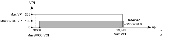
In the example shown in Figure 8-6, the maximum SVCC VPI is 100 and the minimum SVCC VCI is 60. Therefore, VPIs 0 through 100 and VCIs 60 through 16,383 are reserved for SVCCs.
Figure 8-6 Sample SVCC VPI or VCI Range
Each interface negotiates the local values for the maximum SVPC VPI, maximum SVCC VPI, and minimum SVCC VCI with the peer's local value during ILMI initialization. The negotiated values determine the ranges for SVPs and SVCs. If the peer interface does not support these objects or autoconfiguration is turned off on the local interface, the local values determine the range.
To configure a VPI or VCI range for SVCs or SVPs, perform these steps, beginning in global configuration mode:
To confirm the VPI or VCI range configuration, use one of these commands:
show atm interface atm slot/port
Show the ATM interface configuration.
show atm ilmi-status atm slot/port
Show the ILMI status on the ATM interface.
Examples
This example confirms the VPI or VCI range configuration on an ATM interface. The values displayed for ConfMaxSvpcVpi, ConfMaxSvccVpi, and ConfMinSvccVci are local values. The values displayed for CurrMaxSvpcVpi, CurrMaxSvccVpi, and CurrMinSvccVci are negotiated values.
Switch# show atm interface atm 0/0Interface: ATM0/0 Port-type: suni_dualIF Status: DOWN Admin Status: downAuto-config: enabled AutoCfgState: waiting for response from peerIF-Side: Network IF-type: UNIUni-type: Private Uni-version: V3.0Max-VPI-bits: 8 Max-VCI-bits: 14Max-VP: 255 Max-VC: 16383ConfMaxSvpcVpi: 100 CurrMaxSvpcVpi: 100ConfMaxSvccVpi: 100 CurrMaxSvccVpi: 100ConfMinSvccVci: 60 CurrMinSvccVci: 60Svc Upc Intent: pass Signalling: EnabledATM Address for Soft VC: 47.0091.8100.0000.0040.0b0a.2a81.4000.0c80.0000.00Configured virtual links:PVCLs SoftVCLs SVCLs TVCLs PVPLs SoftVPLs SVPLs Total-Cfgd Inst-Conns3 0 0 0 0 0 0 3 0Logical ports(VP-tunnels): 0Input cells: 0 Output cells: 05 minute input rate: 0 bits/sec, 0 cells/sec5 minute output rate: 0 bits/sec, 0 cells/secInput AAL5 pkts: 0, Output AAL5 pkts: 0, AAL5 crc errors: 0This example confirms the peer's local values for VPI or VCI range configuration by displaying the ILMI status on an ATM interface:
Switch# show atm ilmi-status atm 0/0Interface : ATM0/0 Interface Type : Private NNIILMI VCC : (0, 16) ILMI Keepalive : DisabledAddr Reg State: UpAndNormalPeer IP Addr: 172.20.40.232 Peer IF Name: ATM0/0Peer MaxVPIbits: 8 Peer MaxVCIbits: 14Peer MaxVPCs: 255 Peer MaxVCCs: 16383Peer MaxSvccVpi: 255 Peer MinSvccVci: 255Peer MaxSvpcVpi: 48Configured Prefix(s) :47.0091.8100.0000.0010.11ba.9901
Note
![]()
![]()
![]()
![]()
![]()
![]()
![]()
![]()
Posted: Fri Dec 3 13:57:29 PST 2004
All contents are Copyright © 1992--2004 Cisco Systems, Inc. All rights reserved.
Important Notices and Privacy Statement.