|
|

This chapter describes the setup and configuration of the EMS net view, including the following procedures:
After logging in with a valid username and password, EMS presents the net view. (See Figure 4-1.) Net view displays the Cisco 6700 network topology, including all nodes and subnets.

Before EMS can communicate with the NE, you must create a node in the net view. EMS uses nodes to represent each NE in the network.
To create a node:
Step 1 From the net view, select Objects > New Node to create a new node.
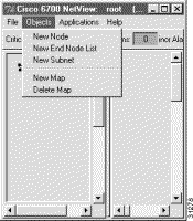
EMS presents the node information window. (See Figure 4-3.)

Step 2 Enter a node name (and optional node alias) for the NE. The node name identifies the node in the net view; the node alias provides additional description information (such as location or organization name).
Step 3 In the IP address text box, enter the primary IP address of the NE. If you are provisioning the NE for the first time, enter the default IP address: 192.168.0.2.
Step 4 In the Type field, and select the proper NE type (6732 or 6705).
Step 5 EMS provides a default node ID number for the NE. Consult your EMS administrator for the correct node ID for use with this NE. Highlight the number and enter a new node ID, or use the slider to change the node ID.
Step 6 Click OK when finished. You will return to the net view. The newly created node will appear as an icon, with the node name and IP address below the icon. (See Figure 4-4.)

Use the following procedures to modify, move, delete, or view a node in EMS.
To move a node, move the cursor to the node you would like to move. While pressing the Shift key, click and drag the node to its new location.
Step 1 Right-click the node icon to bring up the node popup menu. (See Figure 4-5.)
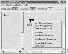
Step 2 Select Display Node Attributes to display the node information window. (See Figure 4-6.)

Step 3 From the node information window, the name, alias, IP address, and node ID can be modified.
Step 1 Right-click the node icon to bring up the node popup menu. (See Figure 4-5.)

Step 2 Select Delete Node to delete the node. EMS asks you to confirm the deletion. (See Figure 4-8.)
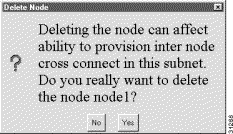
Step 3 Click Yes to delete the node.
Step 1 From the net view menu, select Objects > New End Node List. (See Figure 4-9.)

Step 2 EMS asks for the name of the new end node list. (See Figure 4-10.)

Step 3 Enter a name for the end node list and click OK.
The new end node list icon appears in the net view window. (See Figure 4-11.)
To display the list of nodes in an end node list:
Step 1 From net view, right-click the end node list icon. EMS displays a popup menu. (See Figure 4-12.)
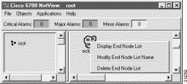
Step 2 Select Display End Node List from the popup menu.
EMS opens the end node list display. (See Figure 4-13.) Each node in the end node list is included in the list, along with its node ID and IP address.
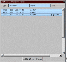
From the end node list display, click any node listing to open the node view for that node.
To add a node to the end node list:
Step 1 Open the end node list display, as shown in the "Displaying an End Node List" section.
Step 2 Click the Add End Node button at the bottom of the display. You will be prompted to enter information for the new node, including a node name and IP address. (See Figure 4-14.)

Step 3 Enter a node name (and optional node alias) for the NE. The node name identifies the node in the net view; the node alias provides additional description information (such as location or organization name).
Step 4 In the IP address text box, enter the primary IP address of the NE. If you are provisioning the NE for the first time, enter the default IP address: 192.168.0.2.
Step 5 In the Type field, and select the proper NE type (6732 or 6705).
Step 6 EMS provides a default node ID number for the NE. Consult your EMS administrator for the correct node ID for use with this NE. Highlight the number and enter a new node ID, or use the slider to change the node ID.
Step 7 Click OK when you are finished. You will return to the end node list display, with the new end node included in the list.
To delete an end node list:
Step 1 In net view, right-click the end node list icon. EMS displays the popup menu. (See Figure 4-15.)

Step 2 Select Delete End Node List from the popup menu. EMS displays a dialog box, asking you to confirm the deletion.
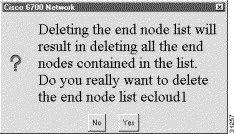
Step 3 Click Yes to delete the end node list.
Subnets are used to segment the Cisco 6700 network into regional or local subnetworks. The use of subnets in EMS allows you to arrange multiple networks in a hierarchy.
To create a new subnet:
Step 1 In net view, select Objects > New Subnet from the menu. (See Figure 4-17.)

EMS prompts you for a subnet name. (See Figure 4-18.)

Step 2 Enter a name and click OK. The net view now contains a subnet icon in the network topology.
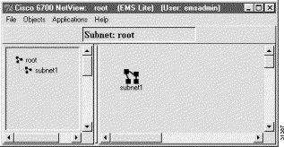
Note the left (hierarchical) frame of the net view, where the new subnet is shown in a hierarchical network view.
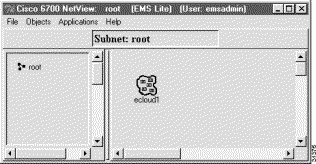
From the net view, double-click the subnet icon. EMS displays the subnet topology in the net view. Note that the name of the subnet is displayed at the top of the right frame. (See Figure 4-20.)

The subnet can now be configured with nodes and additional subnets.
 | Tips Each subnet is represented by two icons---the icon in the network frame (right frame), and the icon in the hierarchical frame (left frame). Either icon can be double-clicked to display the subnet topology. |
Each subnet (including the root network) can be assigned a GIF file depicting the subnet map or other graphic icon. To assign a map (or replace an existing map), select Objects > New Map from the net view of the appropriate subnet. (See Figure 4-21.) To remove an existing map, select Objects > Delete Map.

To return to the root network topology, double-click the root icon in the hierarchical (left) frame. (See Figure 4-20.)

Alternatively, you can click the Go To Upper Layer button, located at the top right of the net view window. This button opens the view for the next-highest network or subnet (as indicated in the hierarchical frame).
![]()
![]()
![]()
![]()
![]()
![]()
![]()
![]()
Posted: Fri Mar 3 15:38:42 PST 2000
Copyright 1989 - 2000©Cisco Systems Inc.