|
|

This section describes the general procedures used to provision cards and lines on the Cisco 6700 NE.
Card and line provisioning is done from the node view of an NE. From the node view, you can provision all cards and lines in the NE.
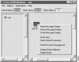
To launch the node view, double-click the node icon, or right-click the node icon and select Node View from the popup menu. (See Figure 5-1.)
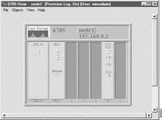
Depending on the chassis type, EMS launches the Cisco 6732 node view (see Figure 5-2) or the Cisco 6705 node view (see Figure 5-3).

If the node ID entered in EMS differs from the current node ID assigned to the NE, EMS reports a node ID conflict. (See Figure 5-4.)

Example: You create a node in EMS net view and assign a node ID of 3, but the Cisco 6700 NE is provisioned with a node ID of 1. When you double-click the node icon, EMS reports a node ID conflict. Selecting Yes changes the NE node ID to 3. Selecting No leaves the NE with its node ID of 1.
If EMS is unable to connect with the NE, you will see a warning message describing the problem. The following list identifies common issues that might prevent the EMS workstation from communicating with the NE:
EMS detects all cards in the Cisco 6732 or Cisco 6705 chassis.
Step 2 From the net view, open the node view of the chassis using one of the following methods:
Step 3 Select View > Refresh Card Display from the menu bar. (See Figure 5-5.)
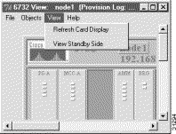
EMS refreshes the node view display to reflect newly inserted cards.
To provision a slot for a particular card in a Cisco 6732 or Cisco 6705 chassis, complete the following steps from node view:
Step 1 Double-click the slot to be provisioned. EMS launches the plugin slot provisioning window. (See Figure 5-6.)

Step 2 In the Designated Card Type field, select the desired card type from the pull-down list. EMS displays only the cards that are compatible with the selected slot. For more information about slot and card compatibility, consult the Cisco 6732 Full Access Device Hardware Installation Guide or the Cisco 6705 Integrated Access Device Hardware Installation Guide.
Step 3 Click Apply to provision the slot.
EMS provides both individual and batch procedures for placing cards in service.
To place an individual card in service, complete the following steps starting in node view:
Step 1 Double-click the card to be placed in service. EMS launches the plugin card provisioning window. (See Figure 5-7.)
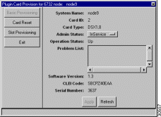
Step 2 Set the Admin Status field to InService.
Step 3 Click Apply to place the card in service.
Step 4 Click the Exit button on the left side of the window to return to node view.
To place cards multiple cards in service using the batch procedure, complete the following steps starting in node view:
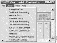
Step 1 Select Objects > Card Batch Provisioning from the node view menu bar. (See Figure 5-8.)
Step 2 EMS displays the card batch provisioning window. (See Figure 5-9.) The Card List lists all cards that the NE has detected as installed.
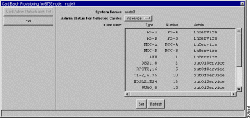
Step 3 In the Admin Status for Selected Cards field, select inService.
Step 4 In the Card List window, select the line cards to be placed in service.
Step 5 Click the Apply button to put the cards in service. EMS works down the list, changing each outOfService to inService.
Step 6 Click the Exit button on the left side of the window to return to node view.
EMS allows one-to-one (1:1) protection of the following broadband cards:
If one card fails, the second card will automatically restore the traffic through the chassis to the backplane. This ensures greater dependablity in the event of a hardware failure.
Broadband protection can only be provisioned on designated broadband slots. Two pairs of slots in the Cisco 6732 chassis are designated for broadband protection:
In addition to provisioning broadband protection with EMS, the protected cards require a special cable, provided with the card, designed specifically for joining the two cards. For more information, see the Cisco 6732 Full Access Device Hardware Installation Guide.
To launch the broadband protection provisioning window, select Objects > Protection Group from the node view menu. (See Figure 5-10.)

EMS launches the protection group provisioning window. (See Figure 5-11.)

Complete the following fields to provision broadband 1:1 protection:
Click Apply to activate broadband 1:1 protection.
To place multiple lines in service, complete the following steps starting in node view:
Step 1 Select Objects > Line Batch Provisioning from the node view menu bar. (See Figure 5-12.)

Step 2 EMS displays the line status assignment window. (See Figure 5-9.)

Step 3 In the Admin Status field, select inService.
Step 4 In the Card Type field, select one of the line card types that are currently installed in the NE. If the selected card type is present, EMS displays the slot numbers for each card in the Card List window. For example, if your NE has FXS/16 cards in slots 3 and 4, selecting the FXS card type will display 3 and 4 in the card list window.
Step 5 In the Card List window, click each card number while holding down the Control key to select (highlight) the card.
Step 6 When all card numbers are selected, click the right arrow next to the card list window. The Result List (on the right side of the window) displays all lines on the selected cards, along with the status (inService or outOfService) of each line. (See Figure 5-14.)
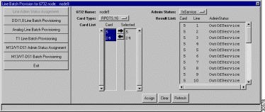
Step 7 In the Result List window, select the lines to be placed in service.
Step 8 After the lines are selected, click the Apply button to put the lines in service. EMS works down the list, changing each outOfService to inService.
Step 9 Return to Step 4 and repeat these steps for each card type present in the NE.
Step 10 Click the Exit button on the left side of the window to return to node view.
Step 11 Select View > Refresh Card Display to update the node view display. Lines that have been placed in service will display a green LED.
To provision a line on a Cisco 6700 line card, double-click the line icon. EMS displays the appropriate line provision window.
The following sections describe basic provisioning for individual lines on the following Cisco 6700 line cards.

In the Line Number field, select the analog line to be provisioned.
Set the following parameters according to your application:
After making changes in the basic provisioning window, click Apply to provision the line. Repeat steps through to provision additional lines on the card.
Step 1 Select Objects > Line Batch Provisioning from the node view menu bar. (See Figure 5-12.)

Step 2 EMS displays the line status assignment window. (See Figure 5-9.)

Step 3 Select Analog Line Batch Provisioning in the function bar. EMS displays the analog line batch provisioning window. (See Figure 5-18.)
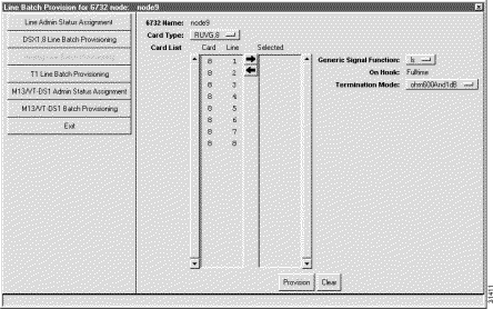
Step 4 Set the Card Type to the card or cards to be provisioned.
Step 5 In the Card List, highlist the lines to be provisioned.
Step 6 Click the the right arrow between the Card List and the Selected list. EMS places the selected lines in the Selected list.
Step 7 Set the following parameters according to your application:
Step 8 Click Apply to provision the lines.

Set the following parameters according to your DSX1 application:
After making changes in the basic provisioning window, click Apply to provision the line.
From the DSX1/8 line provisioning window (see Figure 5-19), click DS0 Signaling to open the DS0 signaling window (see Figure 5-20).
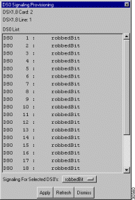
Step 1 Highlight the DS0 channels to be modified.
Step 2 Set the Signaling for Selected DS0s:
Step 3 Click Apply to provision the selected DS0 channels.
Step 1 Select Objects > Line Batch Provisioning from the node view menu bar. (See Figure 5-21.)

Step 2 EMS displays the line status assignment window. (See Figure 5-22.)

Step 3 Select DSX1,8 Line Batch Provisioning in the function bar. EMS displays the DSX1 line batch provisioning window. (See Figure 5-23.)
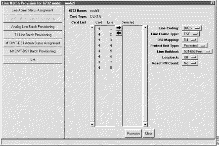
Step 4 In the Card List, highlist the lines to be provisioned.
Step 5 Click the the right arrow between the Card List and the Selected list. EMS places the selected lines in the Selected list.
Step 6 Set the following parameters according to your application:
Set the following parameters according to your DSX1 application:
Step 7 Click Apply to provision the lines.
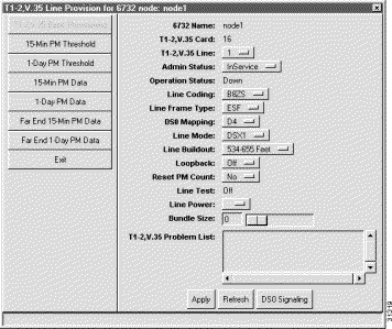
Set the following parameters according to your T1 application:
After making changes in the basic provisioning window, click Apply to provision the line.
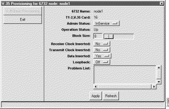
Set the following parameters according to your T1 application:
After making changes in the basic provisioning window, click Apply to provision the line.
Step 1 Select Objects > Line Batch Provisioning from the node view menu bar. (See Figure 5-26.)

Step 2 EMS displays the line status assignment window. (See Figure 5-9.)

Step 3 Select T1 Line Batch Provisioning in the function bar. EMS displays the T1 line batch provisioning window. (See Figure 5-28.)
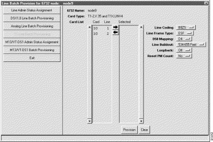
Step 4 Set the Type to VT-DS-1 (STSX1).
Step 5 In the Card List, highlist the lines to be provisioned.
Step 6 Click the the right arrow between the Card List and the Selected list. EMS places the selected lines in the Selected list.
Step 7 Set the following parameters according to your application:
Step 8 Click Apply to provision the lines.
![]()
![]()
![]()
![]()
![]()
![]()
![]()
![]()
Posted: Fri Mar 3 15:43:47 PST 2000
Copyright 1989 - 2000©Cisco Systems Inc.