|
|

This chapter describes the creation of an inter-node data link (INDL) between a local Cisco 6732 node and a remote Cisco 6705 node. An INDL allows the provisioning of a remote node over an established ("nailed-up") connection to the local node.
The provisioning of an INDL requires one node to be designated the local node, and another node designated the remote node. In this example, the Cisco 6732 serves as the local node, and the Cisco 6705 as the remote node. It is also possible to create an INDL between two Cisco 6732 nodes.
Each node must be provisioned with a separate "half link" before the INDL can be used. Complete the following procedures to establish communications with an INDL:
To create a half link from the local node to the remote node, complete the following steps starting in net view:
Step 1 Connect the EMS workstation to the local node (Cisco 6732).
Step 1 Go to the EMS net view. (See Figure 6-1.)

Step 2 Click and drag a line from the local node (Cisco 6732) to the remote node (Cisco 6705). (See Figure 6-2.)

Step 3 This creates a visual link between the two nodes. (See Figure 6-3.)

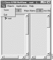
Step 4 From the menu bar, select File > Save to save the visual link.
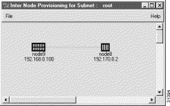
Step 5 Click on the Inter-Node Provision button (located in the upper right corner of the net view window). EMS launches the inter-node provisioning window. (See Figure 6-5.)
Step 6 Double-click the line between the two nodes. EMS launches the inter-node link display. (See Figure 6-6.)
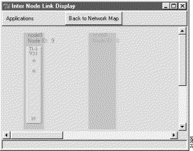
Step 7 Select a line from the local node display that will be provisioned with the half link.
Step 8 Click and drag a visual link from the line on the local node to the remote node. (See Figure 6-7.)
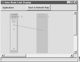
Step 9 After creating the visual link, EMS launches the inter node link provision window. (See Figure 6-8.)
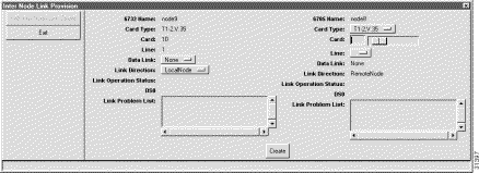
Step 10 In the inter-node link provision window, set the following parameters:
Step 11 Click Create (at the bottom of the window). EMS changes the Create button to Refresh. (See Figure 6-9.)
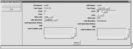
Step 12 Click Exit to close the inter node link provision window. EMS returns to the inter-node link display. (See Figure 6-10.)
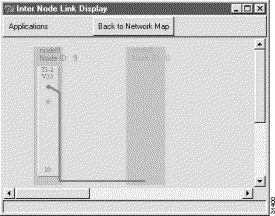
The newly created half link is shown as a blue line connecting the local node and remote node.
Step 13 Click Back to Network Map (at the top of the window) to return to the net view.
After creating the INDL half link on the local node, a similar half link must created on the remote node---in this example, the Cisco 6705.
Step 1 Connect the EMS workstation to the remote node (Cisco 6705).
Step 2 Click on the Inter-Node Provision button (located in the upper right corner of the net view window). EMS launches the inter-node provisioning window. (See Figure 6-11.)

Step 3 Double-click the line between the two nodes. EMS launches the inter-node link display. (See Figure 6-12.)
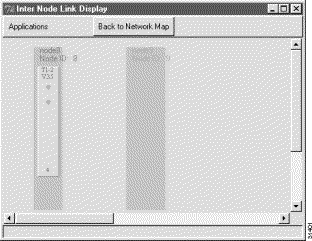
Step 4 Select the line from the remote node display to be provisioned with the half link.
Step 5 Click and drag a visual link from the local line to the remote node. (See Figure 6-13.)

Step 6 After creating the visual link, EMS launches the inter node link provision window. (See Figure 6-14.)
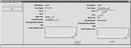
Step 7 In the inter-node link provision window, set the following parameters:
Step 8 Click Create (at the bottom of the window). EMS changes the Create button to Refresh. (See Figure 6-15.)
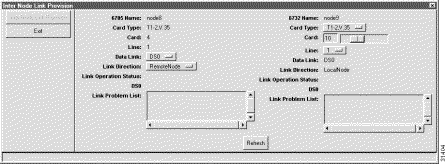
Step 9 Click Exit to close the inter node link provision window. EMS returns to the inter-node link display. (See Figure 6-16.)

The newly created half link is shown as a blue line connecting the remote node and local node.
Step 10 Click Back to Network Map (at the top of the window) to return to the net view. (See Figure 6-17.)

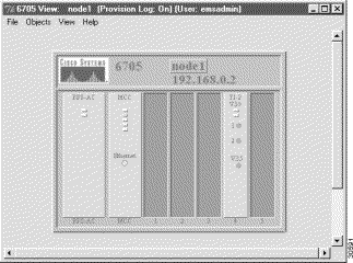
Step 11 Open the remote node (Cisco 6705) by double-clicking the remote node icon in net view. EMS launches the node view of the remote node. (See Figure 6-18.)
Step 12 Double-click the node nameplate. (See Figure 6-19.)
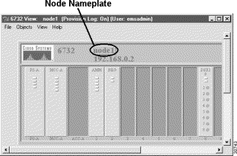
Step 13 EMS launches the NE provision window. (See Figure 6-20.)
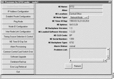
Step 14 From the function bar on the left, click on the Datalink Route Configuration button. This brings up the datalink route configuration window. (See Figure 6-21.)
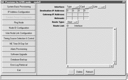
Step 15 Set the following parameters in the datalink route configuration window:
Click Add when finished.
Step 16 Click the Exit button (from the function bar) to return to the node view.
Step 17 Select File > Exit to return to the net view.
Step 18 Using the TCP/IP configuration utility on your EMS workstation, set the Default Gateway to the same address as the local node (Cisco 6732) IP address.
Figure 6-22 shows the TCP/IP configuration window for Windows NT. For the complete TCP/IP configuration procedure, see the "Configure TCP/IP on the EMS Workstation" section.
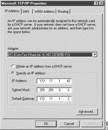
Step 19 Click OK to configure TCP/IP on the EMS workstation, and reboot if necessary.
To verify the INDL has been successfully created, connect a EMS workstation to the local node (Cisco 6732). Open EMS net view and double click on the remote node (the Cisco 6705). The remote node should open, displaying the node view. This means EMS is able to use the INDL to access the remote node.
![]()
![]()
![]()
![]()
![]()
![]()
![]()
![]()
Posted: Fri Mar 3 15:34:58 PST 2000
Copyright 1989 - 2000©Cisco Systems Inc.