|
|

Table Of Contents
FXS/16, RPOTS/16, RUVG/8, ISDN-BRI/8, and MSDSL-2W (2-Wire) Cabling
DSX3/CHNL and STSX1/CHNL Cables
Cabling and Wiring
Power Wiring
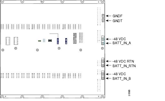
CautionThe following backplane information is provided exclusively for use by a Cisco certified technician or field engineer. Removing the backplane of the Cisco 6732 full access device chassis can void the limited warranty. Please contact Cisco Systems' technical assistance center (TAC) before making any modifications to the chassis.
Figure 3-1 Cisco 6732 Backplane Power Wiring Terminals
Alarm Input and Output Cables
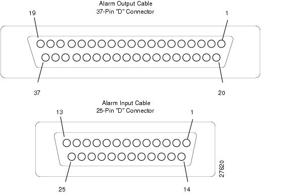
Cisco uses a cable with a 25-pin female D-subconnector for alarm inputs and a cable with a 37-pin female D-subconnector for alarm outputs. Refer to Figure 3-2 for cable specifications.
Figure 3-2 Alarm Input and Output Cables
Alarm Outputs
Six alarm outputs are used to indicate defined system conditions:
•
•
Alarm outputs 7 and 8 are reserved for future use.
To provide alarm notification of a pulled or missing AMM module, the alarm output connector contains a fail-safe or bay alarm relay output (labeled Bay Alarm). This alarm will remain active if power is removed from the bank.
Table 3-1 Alarm Output Assignments
C = Closed, NC = Normally Closed, NO = Normally Open
External Alarm Inputs
There are 16 external alarm inputs available through the alarm input cable, each with a configurable name and severity level. The alarm inputs are configurable via the Element Managment System (EMS). By default, alarm input number 1 is assigned to the remote alarm cut-off (ACO) function.
Table 3-2 Alarm Input Assignments
Backplane Fail-safe Alarm
To provide alarm notification of a pulled or missing AMM module, the alarm output connector contains a fail-safe or bay alarm relay output (labeled Bay Alarm). This alarm will remain active if power is removed from the bank.
Alarm Cut-off
Alarm input number 1 and the ACO push-button on the front panel of the AMM module provide access to the alarm cut-off function. Pushing the ACO push-button toggles the state of the ACO.
If alarm input number 1 is used for the ACO function, you must wire a momentary push-button to the alarm input. Do not use a toggle switch. The momentary push-button serves the same purpose as the ACO button on the AMM module.
If the ACO is in the on state, the AMM ACO LED will light and alarm outputs 3 through 6 will be cleared. Any new alarms will reactivate the corresponding alarm output.
If the ACO is in the off state, the AMM ACO LED will be off and alarm outputs 1 through 3 will remain in their current states.
Alarm Input and Output Wiring
Caution
Figure 3-3 Alarm Connections on the Cisco 6732 Backplane
Line Interface Module Cables
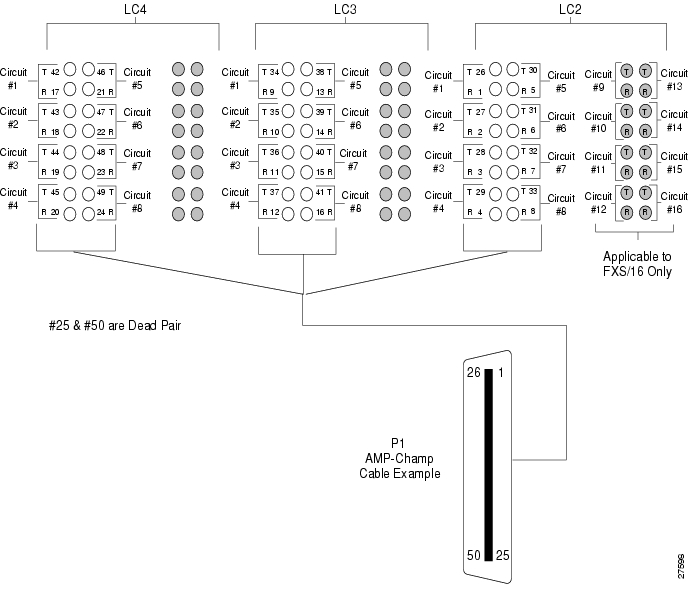
The Cisco 6732 backplane line interface module connections are prewired at the factory with cables that are terminated with 50-wire (25-pair) male RJ-21 connectors (also referred to as AMP-Champ). These cables must be terminated into female RJ-21 cables to mate the two cables. Figure 3-4 shows the pin placements on the male RJ-21 connector.
Figure 3-4 AMP-Champ Pin Assignments
Table 3-3 contains the wiring configuration for Cisco 6732 line interface module cables. The wiring is organized in logical cable groups. Up to three line interface modules can be configured with each cable.
Caution
FXS/16, RPOTS/16, RUVG/8, ISDN-BRI/8, and MSDSL-2W (2-Wire) Cabling
Table 3-4 contains the 2-wire circuit-to-tip/ring legend mapping scheme.
DSX1/8 (4-Wire) Cabling
Table 3-5 contains the DSX1 circuit-to-tip/ring legend mapping scheme.
Subscriber Backplane Wiring
Caution
Figure 3-5 Tip/Ring Legend for RPOTS Termination
Figure 3-6 FXS/16, RPOTS/16, RUVG/8, ISDN-BRI/8, and MSDSL-2W Wiring Configuration
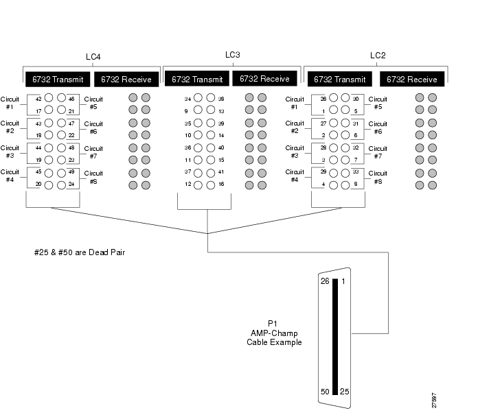
Figure 3-7 DSX1/8 Wiring Configuration
T1-2-V35 Cable
The T1-2-V35 card ships with a 5-foot V.35 cable that provides connectivity to Cisco 1000 and Cisco 4500 series routers. You can order a spare using product number CAB-67-011=. Table 3-6 lists pin assignments for the V.35 cable.
DSX3/CHNL and STSX1/CHNL Cables
The STSX1/CHNL and DSX3/CHNL line interface modules each ship with two 18-inch coaxial SMB female to coaxial BNC male cables. Connect the cables to the transmit (Tx) and receive (Rx) coaxial connectors terminals of the line interface module. You can order a spare using product number CAB-SMB-BNC=. Cisco recommends 75-ohm telecommunications cables for these connections (RG 59/U Type, 20AWG [solid]).
1:1 Protection Cables
One to one (1:1) protection of the STSX1/CHNL and DSX3/CHNL line interface modules is achieved through a pair of coaxial Y cables installed on the Tx and Rx coaxial connectors of the protected modules. You can order a spare pair of 1:1 protection cables using product number CAB-1X1PRO=.
To install 1:1 protection cables, connect the female connectors at each end of the Y cable to the Tx terminals of two adjacent line interface modules. Connect the male connector in the middle of the Y cable to the SMB female coaxial connector of a DSX3/CHNL or STSX1/CHNL cable. Repeat this procedure for the Rx terminals using the other Y cable.
Caution
Note
OC3c-UNI Cables
The OC3c-UNI line interface module has a female duplex SC connector on the faceplate. You must supply a single-mode intermediate reach fiber cable to connect to the connector.
MTAC-TEI Cables
The MTAC-TEI service module uses prewired cables on the Cisco 6732 chassis to connect with third-party test equipment. For information on MTAC-TEI cabling, refer to the Release Notes for Cisco 6700 Series.
![]()
![]()
![]()
![]()
![]()
![]()
![]()
![]()
Posted: Wed Jan 12 14:54:04 PST 2005
All contents are Copyright © 1992--2005 Cisco Systems, Inc. All rights reserved.
Important Notices and Privacy Statement.