|
|

Table Of Contents
Chassis Power Requirements and Power Dissipation
Installing the Cisco 6732 Chassis
Installing the Fan and Filter Assembly (FFA) and Air Ramp
Inserting Service Modules and Line Interface Modules
Inserting the Active BPS-HP Module
Inserting the Standby BPS-HP Module
Inserting the Active MCC Module
Inserting the Standby MCC Module
Inserting a Line Interface Module
Hardware Installation
This chapter contains installation and setup instructions for the Cisco 6732 full access device. These instructions apply to central office terminal (COT) and remote terminal (RT) installations. This chapter should be used as a reference document for customer installation and verification. Specifically, this chapter provides instructions for installing the Cisco 6732 chassis, air ramp, and fan and filter assembly (FFA).
Before You Begin
The following sections contain important safety, site planning, and power requirement information:
•
Chassis Power Requirements and Power Dissipation
Safety Recommendations
When installing the Cisco 6732, observe all caution and warning statements. The following guidelines will help ensure your safety and protect the equipment. However, these guidelines may not cover all potentially hazardous situations you may encounter during system installation.
•
•
•
•
•
Warning
Warning
Input Power Requirements
Use the following guidelines to determine power requirements at your installation site:
•
•
•
•
If a -42.5 VDC to -56 VDC fused power source is not available at your installation site, you must use a third-party power conversion utility (such as a rectifier). Cisco Systems recommends the use of a fuse and alarm panel (FAP) in between the power source and Cisco equipment.
Chassis Power Requirements and Power Dissipation
Table 2-1 contains power requirements for each Cisco 6732 service module. Table 2-2 contains power requirements for each Cisco 6732 line interface module. You must use a -42.5 VDC to -56 VDC power source to supply power to the Cisco 6732.
-48 VDCBPS-HP
20
0.42
20
MCC-STR3
20
0.42
20
MCC-STR4
20
0.42
20
AMM
6
0.13
6
BRG
261
0.54
MTAC-TEI
12
0.25
12
1 20 REN load (BRG card)
To calculate total Cisco 6732 chassis power requirements (in watts) using the worksheet in Table 2-2, insert the quantity of modules or cards in the left column, "Number of Cards." Calculate individual card requirements using the amp figures shown in the "Amps @ -48VDC" column. Forward amp sum totals to "Total Amps" column and total. Combine line interface modules and service module values for overall system power requirement.
To calculate total Cisco 6732 chassis power dissipation using the worksheet in Table 2-2, insert the quantity of modules or cards in the left column, "Number of Cards." Calculate individual line card power dissipation using the amp watts values shown in the "Power Dissipation" column. Forward watt sum totals to the last column on the right and total. Combine service modules and line interface modules for overall system power dissipation.
Space Requirements
Figure 2-1 represents a typical Cisco 6732 rack configuration. The fuse and alarm panel (FAP) is placed at the top of the rack. At least 1-3/4 inches of clearance should be provided between the FAP and the Cisco 6732 bank. The fan and filter assembly (FFA) should be installed directly below the Cisco 6732. An air ramp should be installed directly above the Cisco 6732. The FFA is designed to force air up through the Cisco 6732 chassis, and the air ramp forces heated air to the rear of the rack.
Determine rack spacing requirements for mounting the Cisco 6732 with the FFA touching the under side of the Cisco 6732 and the air ramp touching the top of the Cisco 6732.
Figure 2-1 Cisco 6732 Rack Configuration
•
•
•
Unpacking the Equipment
Unpack the air ramp, FFA, and Cisco 6732 full access device. Inspect these items for damage and make sure you have the required components.
Air Ramp
The air ramp kit should contain the following:
•
•
Fan and Filter Assembly
The fan and filter assembly (FFA) kit should contain the following:
•
•
•
Cisco 6732 Chassis
The Cisco 6732 chassis kit should contain the following:
•
•
•
Put any service modules, line interface modules, or software kits in a convenient place. These will be used later in the installation procedure.
Preassembled Components
•
•
•
•
•
•
For more information about cables on the Cisco 6732 chassis, see Chapter , "Cabling and Wiring." Cisco Systems can provide additional materials upon request (for example, tie wraps and/or velcro straps and Category-5 UTP patch cables.)
Preparing the Cisco 6732 for Mounting in a 23-inch Rack
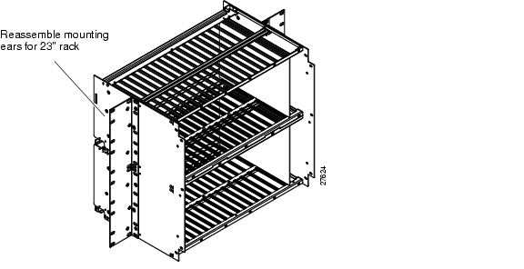
The Cisco 6732 chassis is shipped ready for mounting in a 19-inch rack. If you are using a 23-inch rack, unfasten the Cisco 6732 mounting ears and reassemble them as shown in Figure 2-2. Reassemble the left ear on the left side and the right ear on the right side.
Figure 2-2 Cisco 6732 with Mounting Ears for 23-Inch Rack
Installing the Cisco 6732 Chassis
This section describes the installation of a Cisco 6732 in a COT or RT location. Cisco Systems recommends that the unit be connected to a fused power source.
Note
Step 1
Step 2
Step 3
Step 4
Step 5
Figure 2-3 Cisco 6732 Mounting in a 19-Inch Rack
Installing the Fan and Filter Assembly (FFA) and Air Ramp
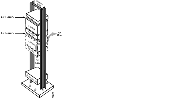
Figure 2-4 shows the proper positioning for the fan and filter assembly (FFA) and air ramp. The fan is designed to force air up though the system. The air ramp is designed to direct air exhaust to the back side of the ramp. Install the fan tray using hardware provided. (See Figure 2-4.)
•
•
Figure 2-4 Cisco 6732 Fan and Filter Assembly (FFA) with Air Ramp
Connecting System DC Power
Cisco Systems recommends that the Cisco 6732 chassis be connected to a fused power source. Verify the circuit breaker on the power source is in the off position. If your power source uses fuses instead of circuit breakers, remove the fuses from the power source.
Note
Step 1
Step 2
Step 3
Step 4
Step 5
Caution
Step 6
Step 7
Figure 2-5 shows a typical power and ground wiring configuration, using a fuse and alarm panel (FAP), grounding busbar, and dual (redundant) power sources.
Figure 2-5 Cisco 6732 Chassis and FFA Power and Ground Wiring
Inserting Service Modules and Line Interface Modules
Caution
To insert a service module or line interface module:
Step 1
Step 2
Step 3
Step 4
Step 5
Step 6
Step 7
Step 8
Removing a Service Module or Line Interface Module
Use the following procedure to remove a service module or line interface module:
Step 1
Step 2
Step 3
Step 4
Step 5
Module Insertion Order
Service modules and line interface modules must be inserted into the chassis in the following order:
1.
2.
3.
4.
5.
6.
7.
Inserting the Active BPS-HP Module
When you insert a BPS-HP module in slot BPS-A, the green PWR LED will light immediately. This indicates that the module is above the minimum -42.5 VDC input voltage threshold.
Any further LED activity indicates module or system status. See Chapter , "Hardware Description," for LED information for the BPS-HP module.
Note
Inserting the Standby BPS-HP Module
When you insert a second (standby) BPS-HP module in slot BPS-B, the green PWR LED will light immediately. This indicates that the module is above the minimum -42.5 VDC input voltage threshold.
Any further LED activity indicates module or system status. See Chapter , "Hardware Description," for LED information for the BPS-HP module.
Inserting the AMM Module
When you insert an AMM module in slot AMM-1, the FAIL LED lights for several seconds and then turns off.
Any further LED activity indicates module or system status. See Chapter , "Hardware Description," for LED information for the AMM module.
Troubleshooting
If the PWR LED does not light, the BPS-HP is not receiving a minimum of -42.5VDC. Measure the input power terminals on the backplane to determine if the Cisco 6732 is receiving a minimum input of -42.5 VDC.
The FUSE LED illuminates if one of the three card fuses is blown.
Note
If a BPS-HP card senses an output short or overvoltage, the module shuts down (providing no voltage to power the LEDs).
If the module fails, remove the module and then reseat it in the bank. If the failure persists, replace the BPS-HP and contact the Cisco Systems technical assistance center (TAC).
Inserting the Active MCC Module
When you insert an MCC module (either MCC-STR3 or MCC-STR4) in slot MCC-A, the following initialization sequence occurs:
1.
2.
3.
4.
5.
6.
Any further LED activity indicates module or system status. See Chapter , "Hardware Description," for LED information for the MCC module.
Inserting the Standby MCC Module
When you insert a second (standby) MCC module (either MCC-STR3 or MCC-STR4) in slot MCC-B, the following initialization sequence occurs:
1.
2.
3.
4.
5.
6.
7.
Note
Any further LED activity indicates module or system status. See Chapter , "Hardware Description," for LED information for the MCC module.
Inserting a Line Interface Module
When you insert a line interface module in an available general-purpose slot, the following initialization sequence occurs:
1.
2.
Any LEDs that remain lit after initialization indicate module or line status. See Chapter , "Hardware Description," for LED information for each line interface module.
Broadband Module Restrictions
Internal cross-connects created on broadband modules DSX3/CHNL, STSX1/CHNL, and OC3c-UNI can prohibit the use of certain general-purpose slots. If you plan to create internal cross-connects between broadband modules, see Table 2-1 for a list of slots that will be disabled.
Table 2-1 Slots Disabled by Internal Broadband Cross-Connects
17
9, 10
18
11, 12
19
13, 14
20
15, 16
Troubleshooting
If the green ACTV LED does not light, the active MCC-STR3 card has not booted up properly.
If the yellow STBY LED does not light, the standby MCC-STR3 card has not completed the database transfer from the active MCC-STR3 card properly.
If an active or standby MCC-STR3 card fails, remove the card and reseat it in the chassis. If the failure persists, replace the MCC-STR3 card and contact the Cisco Systems technical assistance center (TAC).
BRG LED Indicators
The red FAIL LED and the green BUSY LED will light and remain on until the module downloads its code (usually completed in less than 1 second).
After downloading, only the red FAIL LED will be lit while the module initializes (usually completed in less than 1 second).
When initialization is complete, the red FAIL LED will flash, then the green BUSY LED will flash in sequence. This completes the download and initialization process. Any LED status demonstrated after this point will reflect module status.
Troubleshooting
When the red FAIL LED is on, a module-level failure has occurred.
When the red FAIL LED and green BUSY LED flash alternately, the BRG module has been inserted into a slot that is provisioned for another type of module.
When the green BUSY LED is on, the proper ring voltage is applied. The module must be provisioned in service (using the Element Management System) to display this status.
3.
–
–
–
–
If the line interface module has not been provisioned for in service (as may be the case in an initial installation), none of the LEDs will be on after boot up and initialization. The LEDs will light after the module and line(s) have been provisioned in service using the Element Management System (EMS).
Troubleshooting
When the red FAIL LED is on, a module-level failure has occurred.
When the red FAIL LED and green BUSY LED flash alternately, it indicates that the module has been inserted into a slot that has been provisioned for another type of module (provisioning error).
When the green BUSY LED is on, it indicates that the proper ring voltage is applied. The module must be provisioned in service (via Element Management System) to display this status.
If the red FAIL LED does not turn off, the module has not booted up properly.
If a line interface modulefails, remove the card and then reseat it in the bank. If the failure persists, replace the module and contact the Cisco Systems technical assistance center (TAC).
![]()
![]()
![]()
![]()
![]()
![]()
![]()
![]()
Posted: Wed Jan 12 14:51:23 PST 2005
All contents are Copyright © 1992--2005 Cisco Systems, Inc. All rights reserved.
Important Notices and Privacy Statement.