|
|

Table Of Contents
Hardware Description
This chapter describes the Cisco 6732 full access device chassis, and the service modules and line interface modules supported by the Cisco 6732 full access device. This chapter includes the following sections:
•
Overview
–
Overview
The Cisco 6732 full access device multiport-per-slot architecture supports fundamental time division mutliplexing (TDM) and asynchronous transfer mode (ATM) technologies. The Cisco 6732 is compliant with relevant NEBS, ANSI, and Telcordia network element standards. The Cisco 6732 provides the following functionality and services for central office (CO) and large remote terminal (RT) applications:
Digital Loop Carrier
The digital loop carrier (DLC) application uses the Cisco 6732 to accept a variety of voice or data signal sources, multiplexing them onto a common transport medium and de-multiplexing them for delivery to the customer at the far end terminating device.
GR-303 Gateway
The GR-303 gateway application concentrates analog circuits onto a GR-303 interface. The Cisco 6732 uses DSX1 or STS-1 transports to the Class 5 switch and DS1 or DS3 transports to the channel banks. The Cisco 6732 splits the services for delivery to the customer through a remote terminal.
Integrated Access Device
The integrated access device application uses the Cisco 6732 to replace the traditional channel bank unit. The Cisco 6732 can function as a 1/0, 3/1, or 3/1/0 DACS while incorporating voice and data applications on a common platform.
Components and Features
Chassis
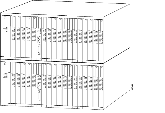
The Cisco 6732 chassis is designed for mounting in 19-inch or 23-inch equipment racks. It is a dual-shelf chassis that holds the following:
Figure 1-1 Cisco 6732 Full Access Device Chassis
Designated-Purpose Slots
The first three slots on the left of each shelf are exclusively designed to support the following Cisco 6732 service modules:
•
•
•
General-Purpose Slots
Each shelf of the Cisco 6732 provides 16 numbered general-purpose slots for use with line interface modules and selected service modules. The first two general purpose slots on the top shelf support the following service modules, in addition to all line interface modules:
•
•
Backplane
The backplane provides the basic architecture and interconnectivity of the Cisco 6732 full access device. The backplane provides all cabling for the Cisco 6732, except for line interface modules with front panel connectors such as the DSX3/CHNL, STSX/CHNL, OC3c-UNI, and T1-2-V35 modules.
Service Modules
Service modules for the Cisco 6732 full access device are hot swappable. They can be inserted into (or removed from) the Cisco 6732 chassis with or without power applied to the system without incurring damage.
The following service modules are available for the Cisco 6732 full access device:
•
•
•
•
•
Bank Power Supply, High Power
The bank power supply, high power (BPS-HP) module supplies power to the main control card (MCC) module and installed service modules, and it passes the -48 VDC current through to the installed line interface modules. The BPS-HP module also provides overcurrent protection for the chassis. One BPS-HP module is required for each MCC module installed in the chassis.
Figure 1-2 BPS-HP Front Panel
Available Slots
The BPS-HP module must be placed in designated-purpose slots BPS-A or BPS-B.
LEDs
The LEDs on the BPS-HP module indicate chassis and module status. (See Table 1-1.)
Connectors
The BPS-HP module does not have any external connectors or interfaces.
Redundancy
Protected (redundant) systems require two BPS-HP modules. One BPS-HP module is inserted in slot BPS-A (to power the service modules in the top shelf) and one in slot BPS-B (to power the service modules in the bottom shelf). If the active BPS-HP module fails, the system switches over to the shelf containing the standby BPS-HP module.
Main Control Card with Stratum 3 Clock
The stratum 3 clock on the main control card (MCC-STR3) module supports synchronization and holdover requirements for the stratum level 3. Systems can also derive timing from an inbound transport span such as a T1, DSX1, or STSX-1.
Figure 1-3 MCC-STR3 Front Panel
The MCC-STR3 module supports the following functions:
•
•
•
•
Available Slots
The MCC-STR3 module must be placed in designated-purpose slots MCC-A or MCC-B.
LEDs
The LEDs on the MCC-STR3 module indicate module and embedded software status. (See Table 1-2.)
Connectors
The MCC-STR3 module provides a 10Base-T Ethernet interface for system management (for systems without an AMM service module).
Main Control Card with Stratum 4 Clock
The stratum 4 clock on the main common control (MCC-STR4) module supports synchronization and holdover requirements for the stratum level 4. Systems can also derive timing from an inbound transport span such as a T1, DSX1, or STSX-1.
Figure 1-4 MCC-STR4 Front Panel
The MCC-STR4 module supports the following functions:
•
•
•
•
Available Slots
The MCC-STR4 module must be placed in designated-purpose slots MCC-A or MCC-B.
LEDs
The LEDs on the MCC-STR4 module indicate module and embedded software status. (See Table 1-3.)
Connectors
The MCC-STR4 module provides a 10BaseT Ethernet interface for system management (for systems without an AMM service module).
Alarm Maintenance and Management
The alarm maintenance and management (AMM) module provides alarm contacts for activation of external circuitry and alarm inputs for basic telemetry entry for connection to the bay alarm panel of a central office. Some alarm inputs are available for customer-defined alarms.
Figure 1-5 Alarm Maintenance and Management Front Panel
The AMM module supports the following functions and features:
•
•
•
•
Available Slots
The AMM module must be placed in general-purpose slot AMM-1.
LEDs
The LEDs on the AMM module indicate system alarm status. (See Table 1-4.)
Alarm Cut-off
The ACO push-button on the AMM front panel provide access to the alarm cut-off function. Pushing the ACO push-button toggles the state of the alarm cut-off and the ACO LED.
If the ACO is in the on state, the AMM ACO LED will light and alarm outputs 3 through 6 will be cleared. Any new alarms will reactivate the corresponding alarm output.
If the ACO is in the off state, the AMM ACO LED will be off and alarm outputs 1 through 3 will remain in their current states.
Connectors
The AMM module provides two interfaces for system management:
•
•
The AMM module transmits system alarm information using the prewired alarm output and alarm input backplane cables. See Chapter 3, "Cabling and Wiring," for alarm cabling information.
Bank Ring Generator
The bank ring generator (BRG) module provides the appropriate ring voltage and synchronization signal to the chassis backplane for use by the RPOTS/16 and RUVG/8 analog line interface modules.
Figure 1-6 BRG Front Panel
•
•
•
•
•
Ring Capacity
The REN number indicates the quantity of ringers which may be connected to a single telephone line and still ring. The total of all RENs of the telephones connected to the one line must not exceed the value 5, or some or all of the ringers may not operate.
Available Slots
The BRG module can be placed in general-purpose slots 1 through 32.
LEDs
The LEDs on the BRG module indicate module status. (See Table 1-5.)
Table 1-5 BRG LED Indicators
FAIL
Red
Off
BRG has failed.
BRG has not failed.
ACTV
Green
Off
BRG is in service, and proper ring voltage is applied.
BRG is not in service.
Alternately blinking FAIL and ACTV LEDs indicate that a slot has been provisioned in EMS for another type of module.
Connectors
The BPS-HP module does not have any external connectors or interfaces.
Metallic Test Access Card, Test Equipment Interface
The metallic test access card, test equipment interface (MTAC-TEI) module provides front panel access to third-party test equipment and buses. The line monitor unit includes relays and plugs that allow external test boxes to monitor signals.
Figure 1-7 MTAC Front Panel
•
•
•
•
•
Available Slots
The MTAC-TEI module must be placed in general-purpose slot MTAC-2.
LEDs
The LEDs on the MTAC-TEI module indicate module status. (See Table 1-6.)
Table 1-6 MTAC-TEI LED Indicators
FAIL
Red
Off
MTAC has failed.
MTAC has not failed.
ACTV
Green
Off
A test is in progress.
No tests are in progress.
Connectors
The MTAC-TEI module offers external interfaces for use with a third-party test probe:
•
•
•
Connectivity is also provided through three pre-wired backplane cables labeled "MTAC (LC2)." These cables provide connectivity to your third-party test equipment; please consult the test equipment documentation for proper cabling. See Chapter 3, "Cabling and Wiring," for alarm cabling information.
Line Interface Modules
Line interface modules for the Cisco 6732 are hot swappable. They can be inserted into (or removed from) the Cisco 6732 chassis with or without power applied to the system without incurring damage. Line interface modules can be inserted in any order.
The following line interface modules are available for the Cisco 6700 series:
•
•
•
•
•
•
•
FXS/16
Each FXS/16 line interface module provides 16 ports of FXS or short-drop POTS/FXS service. The module also provides integrated ring generation and line test functionality.
Figure 1-8 FXS/16 Front Panel
•
•
•
Specifications
•
•
•
•
Available Slots
The FXS/16 module can be placed in general-purpose slots 1 through 32.
LEDs
The LEDs on the FXS/16 module indicate module status. (See Table 1-7.)
Alternately blinking FAIL and BUSY LEDs indicate that a slot has been provisioned in EMS for another type of module.
Connectors
Use the backplane subscriber cables to connect the FXS/16 module. See Chapter 3, "Cabling and Wiring," for subscriber cable information.
RPOTS/16
Each RPOTS/16 line interface module provides 16 circuits of remote POTS service.
Figure 1-9 RPOTS/16 Front Panel
Specifications
•
•
•
•
•
•
Available Slots
The RPOTS/16 module can be placed in general-purpose slots 1 through 32.
LEDs
The LEDs on the RPOTS/16 module indicate module status. (See Table 1-8.)
Alternately blinking FAIL and BUSY LEDs indicate that a slot has been provisioned in EMS for another type of module.
Connectors
Use the backplane subscriber cables to connect the RPOTS/16 module. See Chapter 3, "Cabling and Wiring," for subscriber cable information.
Specifications
RUVG/8
Each RUVG/8 line interface module provides eight circuits supporting POTS, E/UVG, or FXS services.
Figure 1-10 RUVG/8 Front Panel
Specifications
•
•
•
•
Available Slots
The RUVG/8 module can be placed in general-purpose slots 1 through 32.
LEDs
The LEDs on the RUVG/8 module indicate module status. (See Table 1-9.)
Alternately blinking FAIL and BUSY LEDs indicate that a slot has been provisioned in EMS for another type of module.
Connectors
Use the backplane subscriber cables to connect the RUVG/8 module. See Chapter 3, "Cabling and Wiring," for subscriber cable information.
ISDN-BRI/8
Each ISDN-BRI/8 line interface module provides eight U-interface ports of basic rate ISDN service at 144 kbps.
Figure 1-11 ISDN-BRI/8 Front Panel
Available Slots
The ISDN-BRI/8 module can be placed in general-purpose slots 1 through 32.
LEDs
The LEDs on the ISDN-BRI/8 module indicate module and line status. (See Table 1-10.)
Alternately blinking FAIL and BUSY LEDs indicate a slot that has been provisioned in EMS for another type of module.
Connectors
Use the backplane subscriber cables to connect the ISDN-BRI/8 module. See Chapter 3, "Cabling and Wiring," for subscriber cable information.
DSX1/8
The DSX1/8 is a DSX1 interface with eight ports.
Figure 1-12 DSX1/8 Front Panel
The DSX1/8 module supports the following functions and features:
•
•
•
•
•
Specifications
•
•
•
•
Available Slots
The DSX1/8 module can be placed in general-purpose slots 2 through 32.
LEDs
The LEDs on the DSX1/8 module indicate module and line status. (See Table 1-11.)
Alternately blinking FAIL and BUSY LEDs indicate that a slot has been provisioned in EMS for another type of module.
Connectors
Use the backplane subscriber cables to connect the DSX1/8 module. See Chapter 3, "Cabling and Wiring," for subscriber cable information.
T1-2-V35
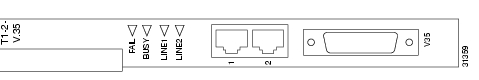
Each T1-2-V35 line interface module provides two ports that can each be provisioned for DSX1 or T1 line buildouts (LBO). The card also features a 26-pin V.35 port on the faceplate of the module.
Figure 1-13 T1-2-V35 Front Panel
Available Slots
The T1-2-V35 module can be placed in general-purpose slots 2 through 32.
LEDs
The LEDs on the T1-2-V35 module indicate module and line status. (See Table 1-12.)
Alternately blinking FAIL and BUSY LEDs indicate that a slot has been provisioned in EMS for another type of module.
Connectors
The T1-2-V35 module provides three interfaces for user traffic:
•
•
DSX3/CHNL
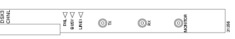
Each DSX3/CHNL line interface module provides DS3 service through a coaxial interface. Channelized 3:1:0 cross-connects are supported. Data transfer rate is 44.736 Mbps.
Figure 1-14 DSX3/CHNL Front Panel
Available Slots
For full bandwidth support, the DSX3/CHNL module must be placed in general-purpose slots 17-20. A DSX3/CHNL module can be placed in slots 2 through 16 or 21 through 32, but only 10 DS1s are available in these slots.
LEDs
The LEDs on the DSX3/CHNL module indicate module and line status. (See Table 1-13.)
Alternately blinking FAIL and BUSY LEDs indicate that a slot has been provisioned in EMS for another type of module.
Connectors
The DSX3/CHNL module provides three interfaces for user traffic:
•
•
•
Each interface uses a BNC connector designed for use with a 75-ohm coaxial cable.
OC3c-UNI
The OC3c-UNI line interface module provides an interface for point-to-point OC3c-UNI data transfer at 155 Mbps.
Figure 1-15 OC3c-UNI Front Panel
Available Slots
For full bandwidth support, the OC3c-UNI module must be placed in general-purpose slots 17 through 20. An OC3c-UNI module can be placed in slots 21 through 32, but available bandwidth is reduced to 30 Mbps.
Note
LEDs
The LEDs on the OC3c-UNI module indicate module and line status. (See Table 1-14.)
Connectors
The OC3c-UNI module provides two user traffic interfaces using a female duplex SC connector. These bidirectional optical ports accommodate single-mode intermediate reach fiber cable.
STSX1/CHNL
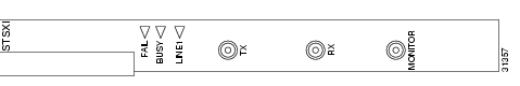
Each STSX1/CHNL line interface module provides an STS-1 interface supporting channelized DS1/DS0 service at 51.84 Mbps. Channelized 3:1:0 cross-connects are supported.
Figure 1-16 STSX1/CHNL Front Panel
Available Slots
For full bandwidth support, the STSX1/CHNL module must be placed in general-purpose slots 17 through 20. An STSX1/CHNL module can be placed in slots 2 through 16 or slots 21 through 32, but only 10 DS1s are available in these slots.
LEDs
The LEDs on the STSX1/CHNL module indicate module and line status. (See Table 1-15.)
Connectors
The DSX3/CHNL module provides three interfaces for user traffic:
•
•
•
Each interface uses a BNC connector designed for use with a 75-ohm coaxial cable.
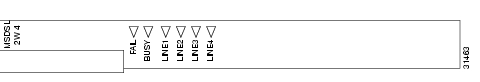
MSDSL-2W
Each MSDSL-2W provides 2-wire MSDSL service to four subscriber ports at transfer rates up to 2.3 Mbps.
Figure 1-17 MSDSL-2 Front Panel
The MSDSL provides 4 independent CAP MSDSL interfaces capable of payload rates of 72 kbps to 2320 kbps. Each interface can be independently provisioned for the following:
•
•
•
•
The primary application of this card is to provide single pair copper transport between 6732 nodes or between a 6732 node and a Telmax CPE device.
Available Slots
The MSDSL-2W module can be placed in general-purpose slots 2 through 32.
LEDs
The LEDs on the MSDSL-2W module indicate module and line status. (See Table 1-16.)
Connectors
Use the backplane subscriber cables to connect the MSDSL-2W module. See Chapter 3, "Cabling and Wiring," for subscriber cable information.
![]()
![]()
![]()
![]()
![]()
![]()
![]()
![]()
Posted: Wed Jan 12 16:00:12 PST 2005
All contents are Copyright © 1992--2005 Cisco Systems, Inc. All rights reserved.
Important Notices and Privacy Statement.