|
|

This chapter contains installation and setup instructions for the Cisco 6705 integrated access device. These instructions apply to customer premises equipment (CPE) and remote terminal (RT) installations. This chapter should be used as a reference document for customer installation and verification. Specifically, this chapter provides instructions for installing the Cisco 6705 integrated access device and the optional battery backup equipment.
The following sections contain important safety, site planning, and power requirement information:
When installing the Cisco 6705, observe all caution and warning statements. The following guidelines will help ensure your safety and protect the equipment. However, these guidelines might not cover all potentially hazardous situations you might encounter during system installation.
 |
Warning Only trained and qualified personnel should be allowed to install or replace this equipment. |
|
Warning Before working on a chassis or working near power supplies, unplug the power cord on AC units; disconnect the power at the circuit breaker on DC units. |
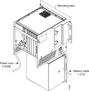
The Cisco 6705 can be powered with AC or DC input power. Typically, AC power is used as the primary power source (from the AC power connector on the BPS-AC card front panel) and DC power is used as the secondary power source (from the battery backup unit).
The Cisco 6705 BPS-AC service module includes an AC/DC converter.
Table 2-1 contains power requirements for each Cisco 6705 service module. Table 2-2 contains power requirements for each Cisco 6705 line interface module. You must use a -42.5 VDC to -56 VDC power source to supply power to the Cisco 6705 integrated access device.
| Number of Cards | Service Module | Power (Watts) | Amps @ -48 VDC | Power Dissipation (Watts) | Total Amps | Total Power Dissipation (Watts) |
|---|---|---|---|---|---|---|
| BPS-AC | 20 | 0.42 | 20 |
|
|
| MCC-INT | 20 | 0.42 | 20 |
|
|
| BRG | 261 | 0.54 |
|
|
|
| 120 REN load (BRG card) |
| Number of Cards | Line Interface Module | Power (Watts) | Amps @ -48 VDC | Power Dissipation (Watts) | Total Amps | Total Power Dissipation (Watts) |
|---|---|---|---|---|---|---|
| DSX1/8 | 10 | 0.21 | 10 |
|
|
| DSX3/CHNL | 11 | 0.23 | 11 |
|
|
| FXS/16 | 16 | 0.33 | 16 |
|
|
| ISDN-BRI/8 | 12 | 0.25 | 12 |
|
|
| OC3c-UNI | 12 | 0.31 | 15 |
|
|
| RPOTS/16 | 16 | 0.58 | 16 |
|
|
| RUVG/8 | 11 | 0.23 | 11 |
|
|
| STSX1/CHNL | 11 | 0.23 | 11 |
|
|
| T1-2-V35 | 20 | 1.25 | 17 |
|
|
To calculate total Cisco 6705 chassis power requirements (in watts) using the worksheet in Table 2-2 , insert the quantity of modules or cards in the first column on the left, "Number of Cards." Calculate individual card requirements using the amp figures shown in the "Amps @ -48VDC" column. Forward amp sum totals to "Total Amps" column and total. Combine line interface modules and service module values for overall system power requirements.
To calculate total Cisco 6705 chassis power dissipation using the worksheet in Table 2-2 , insert the quantity of modules or cards in the left column, "Number of Cards." Calculate individual line card power dissipation using the amp watts values shown in the "Power Dissipation" column. Forward watt sum totals to the last column on the right and total. Combine service modules and line interface modules for overall system power dissipation.
Unpack the Cisco 6705 integrated access device and battery box. Inspect these items for damage and make sure you have the required components.
The Cisco 6705 installation kit should contain the following:
Put any service modules, line interface modules, or software kits in a convenient place. These will be used later in the installation procedure.
The battery box installation kit should contain the following:
The following sections describe mounting procedures for the Cisco 6705 and battery box:
A piece of 3/4-inch plywood, painted with fire retardant paint, must be used between the chassis and the wall.
Step 1 Put the wall mounting template on a 3/4-inch plywood board painted with fire retardant paint.
Step 2 Use the template as a guide to drill holes for the mounting wood screws.
Step 3 Hold the Cisco 6705 chassis against the plywood, and use the four wood screws to fasten the chassis to the plywood.
 |
Caution To prevent thermal damage to the Cisco 6705, the top of the unit must remain clear at all times. No objects (papers, tools, or other network elements) should be placed on top of the Cisco 6705. The open top chassis design allows the Cisco 6705 to maintain acceptable operating temperatures. |
Step 4 Repeat these steps for the battery box. The battery box should be mounted approximately 6 to 8 inches below the Cisco 6705 chassis.
The Cisco 6705 integrated access device chassis is equipped with dual-purpose mounting ears. Before mounting the Cisco 6705 chassis in a 19-inch rack, the mounting ears must be removed and reattached to the chassis. (See Figure 1-2.)
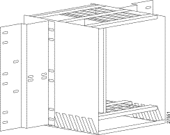
Complete the following tasks to mount the Cisco 6705 in a 19-inch rack:
Step 2 Place the Cisco 6705 on the set screws.
Step 3 Secure the Cisco 6705 to the rack with the four provided rack screws (12-24 x 3/8 inch).
 |
Note The battery box is not configured for mounting in a 19-inch rack. Cisco Systems recommends that you place the battery box on a rack shelf near the Cisco 6705 chassis. |
Figure 1-3 shows the power and ground connectors on the Cisco 6705 chassis.

To connect power and ground wiring for the Cisco 6705 and battery box:
Step 2 To test the ground wiring, use a digital multimeter to test the Cisco 6705 chassis against the equipment rack. Resistance should be less than 1 ohm.
Step 3 Connect the AC power cord from the BPS/AC to a 110 VAC power source.
Step 4 The green PWR LED will light immediately. This indicates that the module is receiving.
|
Note Any further LED activity on the BPS-AC module indicates module or system status. See Chapter , "Product Overview," for LED information for the BPS-AC module. |
Step 5 Connect the battery box output power cable to the battery box terminal on the Cisco 6705 chassis.
|
Caution To prevent electrostatic discharge damage to the Cisco 6705 chassis and components, you must wear an ESD-preventative strap when inserting or removing modules. Place the strap on your wrist, and connect the wire an appropriate ground, such as an equipment. The Cisco 6705 chassis provides a strap insert connection located directly above the BPS-A card slot, at the upper left corner of the chassis. |
To insert a service module or line interface module:
Step 2 Attach an ESD-preventive strap between you and the chassis surface.
Step 3 Hold the service module vertically, with the faceplate toward you and the backplane connectors away from you. Ensure that the module is right side up by noting the lettering on the faceplate.
Step 4 Carefully align the upper and lower edges of the module with the upper and lower guides in the chassis.
Step 5 Gently slide the module into the slot until the lever (at the upper left of the module faceplate) touches the chassis.
Step 6 Lift the lever up and slide the module into the slot until it makes contact with the backplane.
Step 7 Secure the module by pressing the lever down.
Step 8 Connect any cables to cable interfaces on the faceplate.
To remove a service module or line interface module:
Step 2 Remove any connections to the module. Be sure to cover any fiber optic connections to prevent contamination from moisture or dirt.
Step 3 Lift the lever up to unseat the module.
Step 4 Grasp the module faceplate, and carefully slide the module out of the slot. Avoid damaging the connectors on the rear of the module.
Step 5 Place the module on an anti-static surface.
Service modules and line interface modules must be inserted into the chassis in the following order:
1. Main Control Card (MCC-INT) module in slot MCC
2. Remaining service modules and line interface modules in available general-purpose slots.
If the PWR LED does not light, the BPS-HP is not receiving a minimum of -42.5VDC. Measure the input power terminals on the backplane to determine if the Cisco 6732 is receiving a minimum input of -42.5 VDC.
The FUSE LED illuminates if one of the three card fuses is blown.
|
Note These fuses are not field replaceable. |
If a BPS-HP card senses an output short or overvoltage, the module shuts down (providing no voltage to power the LEDs).
If the module fails, remove the module and then reseat it in the bank. If the failure persists, replace the BPS-HP and contact the Cisco Systems technical assistance center (TAC).
When you insert an MCC-INT module in slot MCC, the following initialization sequence occurs:
1. The red FAIL LED will light immediately.
2. All LEDs on the MCC-INT module then light up simultaneously and turn off.
3. The LEDs will perform a "walk-up" sequence, beginning from the bottom LED (SYNC) to the top LED (FAIL).
4. After the walk-up sequence is completed, the red FAIL LED and the green ACTV LED will remain on while the MCC-INT module boots up and achieves active status. The boot-up process might take 20 to 30 seconds to complete.
5. When boot-up is complete, the green ACTV LED will light and remain on.
6. After the MCC-INT module boots up, the green BUSY LED on the BPS-AC module should light. The BUSY LED indicates that the BPS-AC module is supplying power to the MCC-INT module.
Any further LED activity indicates module or system status. See Chapter , "Product Overview," for LED information for the MCC-INT module.
When you insert a line interface module in an available general-purpose slot, the following initialization sequence occurs:
1. The red FAIL LED and the green BUSY LED light and remains on while the module downloads the internal software from the active MCC module.
2. After download, all of the LEDs will flash in sequence from top to bottom.
Any LEDs that remain lit after initialization indicate module or line status. See Chapter , "Product Overview," for LED information for each line interface module.
![]()
![]()
![]()
![]()
![]()
![]()
![]()
![]()
Posted: Tue Feb 13 08:17:35 PST 2001
All contents are Copyright © 1992--2001 Cisco Systems, Inc. All rights reserved.
Important Notices and Privacy Statement.