|
|

Table Of Contents
Using the EXEC Command Interpreter
Performing a Basic Configuration
Customizing the 6E3 Line Card Configuration
Using show Commands to Verify the New Interface Status
Using the ping Command to Verify Network Connectivity
Configuring the 6E3 Line Card
To continue your 6E3 line card installation, you must configure the serial interfaces.
This chapter contains the following sections:
•
Using the EXEC Command Interpreter
Using the EXEC Command Interpreter
You modify the configuration of your router through the software command interpreter called the EXEC (also called enable mode). You must enter the privileged level of the EXEC command interpreter with the enable command before you can use the configure command to configure a new interface or change the existing configuration of an interface. The system prompts you for a password if one has been set.
The system prompt for the privileged level ends with a pound sign (#) instead of an angle bracket (>). At the console terminal, use the following procedure to enter the privileged level:
Step 1
Router> enable
Password:
Step 2
When you enter the correct password, the system displays the privileged-level system prompt (#):
Router#To configure the new interfaces, proceed to the "Configuring the Interfaces" section.
Configuring the Interfaces
After you verify that the new 6E3 line card is installed correctly (the STATUS LED turns green), use the privileged-level configure command to configure the new interfaces. Have the following information available:
•
•
•
•
•
If you installed a new 6E3 line card or if you want to change the configuration of an existing interface, you must enter configuration mode to configure the new interfaces. If you replaced a 6E3 line card that was previously configured, the system recognizes the new interfaces and brings each of them up in their existing configuration.
For a summary of the configuration options available and instructions for configuring interfaces on a 6E3 line card, refer to the appropriate configuration publications listed in the "Related Documentation" section on page viii.
You execute configuration commands from the privileged level of the EXEC command interpreter, which usually requires password access. Contact your system administrator, if necessary, to obtain password access. (See the "Using the EXEC Command Interpreter" section for an explanation of the privileged level of the EXEC.)
This section contains the following subsections:
•
•
Shutting Down an Interface
Before you remove an interface that you will not replace, or replace line cards, use the shutdown command to shut down (disable) the interfaces to prevent anomalies when you reinstall the new interface processor. When you shut down an interface, it is designated administratively down in the show command displays.
Follow these steps to shut down an interface:
Step 1
Step 2
Router# configure terminalEnter configuration commands, one per line. End with CNTL/Z.Router(config)#Step 3
When you have finished, press Ctrl-Z—hold down the Control key while you press Z—or enter end or exit to exit configuration mode and return to the EXEC command interpreter.
Note
Step 4
Router# copy running-config startup-config[OK]Router#The system displays an OK message when the configuration has been stored in NVRAM.
Step 5
Step 6
a.
b.
Use the copy running-config startup-config command.c.
show interfaces command followed by the interface type and interface address of the interface.For complete descriptions of software configuration commands, refer to the publications listed in the "Related Documentation" section on page viii.
Performing a Basic Configuration
Following are instructions for a basic configuration: enabling an interface and specifying IP routing. You might also need to enter other configuration subcommands, depending on the requirements for your system configuration and the protocols you plan to route on the interface. For complete descriptions of configuration subcommands and the configuration options available for serial interfaces, refer to the appropriate software documentation.
In the following procedure, press the Return key after each step unless otherwise noted. At any time you can exit the privileged level and return to the user level by entering disable at the prompt as follows:
Router# disableRouter>
Step 1
Router# configure terminalEnter configuration commands, one per line. End with CNTL/Z.Router(config)#Step 2
Step 3
Router(config-if)# ip address 10.0.0.0 10.255.255.255Step 4
Step 5
Step 6
Step 7
Step 8
Router# copy running-config startupup-config[OK]Router#This completes the procedure for creating a basic configuration.
Table 4-4 shows the default values for the 6E3 line card serial interfaces.
Customizing the 6E3 Line Card Configuration
There are two sides to the network, a local network side and a remote customer side, or near and far ends. The 6E3 line card supports third-party data service units (DSUs), Internet Service Provider (ISP)-provided E3 lines, and so on. The configuration parameter default values in the 6E3 line card port interfaces must match the remote DSUs on your network. Table 4-5 shows the configuration parameters.
Note
Verifying Local and Remote E3 Port Settings
You can use telnet to determine the DSU mode settings on the remote E3 port. Once you verify the remote E3 port settings, you can negotiate changing configuration parameters so that DSU mode settings are the same on both the local and remote E3 ports.
Selecting a DSU Mode
The DSU mode supports two third-party DSU vendors—Digital Link and Kentrox—and the default DSU mode, Cisco. If you use a DSU to make the connection between the Cisco 7304 router and another device, the local E3 port configuration must match the remote E3 port configuration. Therefore, if the remote E3 port uses the Kentrox vendor, a request is sent to the local E3 port to change the DSU mode to Kentrox, either by manually entering the dsu mode configuration command and specifying the Kentrox DSU or by using the Cisco Remote Connection Management (CRCM) feature to remotely configure the remote E3 port. If you make a direct connection between a Cisco 7304 router and another device, you can use the Cisco DSU mode.
Configuring the DSU Bandwidth Range
The DSU bandwidth range is from 0 to 34010 kbps. The local port and the remote port must have matching configurations. Therefore, if you reduce the effective bandwidth to 3000 on the local port, you must do the same on the remote port by entering the dsu bandwidth interface configuration command.
In interface configuration mode, reduce effective bandwidth (range of 0 to 34010 kbps) by entering the dsu bandwidth configuration subcommand, as in the following example:
Router(config-if)# dsu bandwidth 3000Use the no form of this command to return to the default, 34010.
Note
Enabling Payload Scrambling
Payload (data) scrambling converts the data received by the local or remote E3 ports from the Digital Link and Kentrox third-party DSU vendor modes as well as the default, Cisco mode. To enable payload scrambling on the local and remote E3 ports, you must enter the scramble interface configuration command. If you do not enter the scramble command, payload scrambling remains disabled by default on the local and remote E3 ports.
Configuring Cyclic Redundancy Checks
Table 4-6 summarizes cyclic redundancy check (CRC) commands. For more information, see the remainder of this section.
CRC is an error-checking technique that uses a calculated numeric value to detect errors in transmitted data. All interfaces use a 16-bit CRC by default but also support a 32-bit CRC. The sender of a data frame calculates the frame check sequence (FCS). Before it sends a frame, the sender appends the FCS value to the message. The receiver recalculates the FCS and compares its calculation to the FCS from the sender. When the CRC on a received frame is not correct, the frame is dropped. The card does not send a request to the remote end to transmit the frame. (A higher layer protocol is required to implement the retransmission.)
Enable 32-bit CRC using the crc 32 command. Before you can enable 32-bit CRC, you must use the interface serial command (followed by the interface address of the interface) to select the interface on which you want to enable 32-bit CRC. This command functions in the same way on all supported platforms.
In the example that follows, 32-bit CRC is specified:
Router(config-if)# crc 32The preceding command example applies to all systems in which the 6E3 line card is supported.
Use the no crc 32 command to disable the 32-bit CRC setting and return the interface to the default 16-bit CRC setting.When you have finished, press Ctrl-Z—hold down the Control key while you press Z—or enter end or exit to exit configuration mode and return to the EXEC command interpreter prompt. Then write the new configuration to NVRAM using the copy running-config startup-config command.
Note
For command descriptions, refer to the Configuration Fundamentals Configuration Guide publication. For more information, see the "Obtaining Additional Publications and Information" section on page xi and the "Obtaining Additional Publications and Information" section on page xi.
Configuring the Clock Source
The only exception for matching local and remote E3 port configurations is that the clock sources must be set opposite each other. Therefore, if you enter the clock source internal command for the local E3 port, you must enter clock source line for the remote E3 port.
Defining the DSU Mode
In interface configuration mode, define the DSU interoperability mode by entering the dsu mode [cisco | digital-link | kentrox ] configuration subcommand, as in the following example:
Router(config-if)# dsu mode ciscoUse the no form of this command to return to the default, cisco.
Note
Also see the "Interoperability Guidelines for 6E3 Line Card DSUs" section on page 1-3 for information regarding DSU feature compatibilities.
Enabling E3 Scrambling
In interface configuration mode, enable E3 scrambling by entering the scramble configuration subcommand, as in the following example:
Router(config-if)# scrambleUse the no form of this command to restore the default value, scramble.
Note
Also see the "Interoperability Guidelines for 6E3 Line Card DSUs" section on page 1-3 for information regarding DSU feature compatibilities.
Checking the Configuration
After configuring the new interface, use the show commands to display the status of the new interface or all interfaces, and use the ping and loopback commands to check connectivity. This section includes the following subsections:
•
•
•
Using show Commands to Verify the New Interface Status
Table 4-7 demonstrates how you can use the show commands to verify that new interfaces are configured and operating correctly and that the 6E3 line card appears in them correctly. Sample displays of the output of selected show commands appear in the sections that follow. For complete command descriptions and examples, refer to the publications listed in the "Related Documentation" section on page viii.
Note
If an interface is shut down and you configured it as up, or if the displays indicate that the hardware is not functioning properly, ensure that the interface is properly connected and terminated. If you still have problems bringing up the interface, contact a service representative for assistance. This section includes the following subsections:
•
•
•
Choose the subsection appropriate for your system. Proceed to the "Using the ping Command to Verify Network Connectivity" section when you have finished using the show commands.
Using the show version Command
Display the configuration of the hardware, the Cisco IOS software version, the names and sources of configuration files, and the boot images by using the show version command.
Note
Cisco 7304 Routers
Following is an example of the show version command from a Cisco 7304 router with the 6E3 line card:
WS_2_DS3_1600 #show versionCisco Internetwork Operating System SoftwareIOS (tm) 7300 Software (C7300-JS-M), Version 12.2(20S)Copyright (c) 1986-2001 by cisco Systems, Inc.Compiled Thu 20-Dec-03 03:25 by cvaImage text-base:0x4000878, data-base:0x42794000ROM:System Bootstrap, Version 12.1(12r)EX1,RELEASE SOFTWARE (fc1)Currently running ROMMON from ROM 0WS_@_DS3_1600 uptime is 3 hours, 50 minutesSystem returned to ROM by reloadSystem image file is "disk0:c7300-js-mzcisco 7300 (NSE100) processor (revision E) with 114688K/16384K bytes of memory.Processor board ID SCA0702004VR7000 CPU at 350Mhz, Implementation 39, Rev 3.2, 256KB L2, 1024KB L3 Cache4 slot midplane, Version 67.49Last reset from software reset or reloadBridging software.X.25 software, Version 3.0.0.SuperLAT software (copyright 1990 by Meridian Technology Corp).TN3270 Emulation software.PXF processor tmc0 running 'system:pxf/ucode1' v1.4 is activePXF processor tmc1 running 'system:pxf/ucode1' v1.4 is active1 FastEthernet/IEEE 802.3 interface(s)2 Gigabit Ethernet/IEEE 802.3 interface(s)12 Serial network interface(s)1 Packet over Sonet network interface(s)509K bytes of non-volatile configuration memory.16064K bytes of ATA compact flash in bootdisk (Sector size 512 bytes).31360K bytes of ATA compact flash in disk0 (Sector size 512 bytes).Configuration register is 0x0Using the show diag (slot) Command
Display the types of line cards installed in your system (and specific information about each) using the show diag slot command.
Note
Cisco 7304 Routers
Following is an example of the show diag slot command that shows the 6E3 line card in slot 2 of a Cisco 7304 router:
Router# show diag 2Slot 2:E3 Line Card, 6 portsLine Card state:ActiveInsertion time:23:39:27 agoBandwidth points:204060EEPROM contents at hardware discovery:Hardware Revision :3.0Unknown Field (type 0046):00 00PCB Serial Number :CAB0548LLN5Part Number :73-5938-04Board Revision :A0Fab Version :02RMA Test History :00RMA Number :0-0-0-0RMA History :00Deviation Number :0-0Product Number :7300-6E3Top Assy. Part Number :68-0000-00Manufacturing Test Data :00 00 00 00 00 00 00 00Field Diagnostics Data :00 00 00 00 00 00 00 00Calibration Data :Minimum:0 dBmV, Maximum:0 dBmVCalibration values :EEPROM format version 4EEPROM contents (hex):0x00:04 FF 40 03 E2 41 03 00 46 00 00 C1 8B 43 41 420x10:30 35 34 38 4C 4C 4E 35 82 49 17 32 04 42 41 300x20:02 02 03 00 81 00 00 00 00 04 00 80 00 00 00 000x30:CB 94 37 33 30 30 2D 36 45 33 20 20 20 20 20 200x40:20 20 20 20 20 20 87 44 00 00 00 C4 08 00 00 000x50:00 00 00 00 00 C5 08 00 00 00 00 00 00 00 00 C80x60:09 00 00 00 00 00 00 00 00 00 C7 7C F6 49 44 350x70:00 00 00 00 00 00 00 00 00 00 00 00 07 08 64 320x80:28 37 26 09 C4 64 32 28 32 DD 0C E4 64 32 28 430x90:24 2E E0 AA 82 64 F4 24 00 00 00 00 00 00 00 000xA0:00 00 00 00 00 00 F4 B9 FF FF FF FF FF FF FF FF0xB0:FF FF FF FF FF FF FF FF FF FF FF FF FF FF FF FF0xC0:FF FF FF FF FF FF FF FF FF FF FF FF FF FF FF FF0xD0:FF FF FF FF FF FF FF FF FF FF FF FF FF FF FF FF0xE0:FF FF FF FF FF FF FF FF FF FF FF FF FF FF FF FF0xF0:FF FF FF FF FF FF FF FF FF FF FF FF FF FF FF FF0x100:FF FF FF FF FF FF FF FF FF FF FF FF FF FF FF FF0x110:FF FF FF FF FF FF FF FF FF FF FF FF FF FF FF FF0x120:FF FF FF FF FF FF FF FF FF FF FF FF FF FF FF FF0x130:FF FF FF FF FF FF FF FF FF FF FF FF FF FF FF FF0x140:FF FF FF FF FF FF FF FF FF FF FF FF FF FF FF FF0x150:FF FF FF FF FF FF FF FF FF FF FF FF FF FF FF FF0x160:FF FF FF FF FF FF FF FF FF FF FF FF FF FF FF FF0x170:FF FF FF FF FF FF FF FF FF FF FF FF FF FF FF FF0x180:FF FF FF FF FF FF FF FF FF FF FF FF FF FF FF FF0x190:FF FF FF FF FF FF FF FF FF FF FF FF FF FF FF FF0x1A0:FF FF FF FF FF FF FF FF FF FF FF FF FF FF FF FF0x1B0:FF FF FF FF FF FF FF FF FF FF FF FF FF FF FF FF0x1C0:FF FF FF FF FF FF FF FF FF FF FF FF FF FF FF FF0x1D0:FF FF FF FF FF FF FF FF FF FF FF FF FF FF FF FF0x1E0:FF FF FF FF FF FF FF FF FF FF FF FF FF FF FF FF0x1F0:FF FF FF FF FF FF FF FF FF FF FF FF FF FF FF FFFPGA information:Current FPGA version :00.16IOS bundled FPGA version :00.16CPLD version :01.02LC recoveries happened so far:1LC Crash History:LC 2, LC Santa Ana, channel A, error counters:SL0 SL1 SL2 SL3Reframe: [ 0 0 0 0 ]Overrun: [ 0 0 0 0 ]Underrun: [ 0 0 0 0 ]OOB: [ 0 0 0 0 ]Disparity: [ 0 0 0 0 ]Missing_Ctrl_Code: [ 0 0 0 0 ]Chip access errors:[ 0 0 0 0 ]LC 2, NSE Santa Ana 0, channel A, error counters:SL0 SL1 SL2 SL3Reframe: [ 0 0 0 0 ]Overrun: [ 0 0 0 0 ]Underrun: [ 0 0 0 0 ]OOB: [ 0 0 0 0 ]Disparity: [ 0 0 0 0 ]Missing_Ctrl_Code: [ 0 0 0 0 ]Chip access errors:[ 0 0 0 0 ]Linecard interrupt counters:Egress droped packet = 11 (23:41:58 ago)Alarms = 30 (23:56:13 ago)Egress hw error = 10 (23:41:58 ago)Linecard egress hardware error counters:Pkt buffer invalid i/p hdr = 10 (23:41:58 ago)No sop flag at the packet hdr = 4 (23:44:24 ago)Port id error = 10 (23:41:58 ago)Router#Using the show interfaces Command
The show interfaces command displays status information (including the physical slot and interface address) for the interfaces you specify. The example that follows specifies serial interfaces.
Note
Cisco 7304 Routers
Following is an example of the show interfaces command for Cisco 7304 routers. In this example, the serial interfaces (0 to 5) are on a 6E3 line card in slot 1, also, the status information for interfaces 1 through 5 is omitted. (Interfaces are administratively shut down until you enable them.)
Router #sho interfaces serial 2/1Serial2/1 is up, line protocol is upHardware is Packet over E3Internet address is 150.2.2.1/24MTU 4470 bytes, BW 34009 Kbit, DLY 200 usec,reliability 255/255, txload 1/255, rxload 1/255Encapsulation HDLC, crc 16, loopback setKeepalive not setLast input 21:04:19, output 21:04:19, output hang neverLast clearing of "show interface" counters 16:31:30Input queue:0/75/0/0 (size/max/drops/flushes); Total output drops:15263Queueing strategy:fifoOutput queue:0/40 (size/max)5 minute input rate 0 bits/sec, 0 packets/sec5 minute output rate 0 bits/sec, 0 packets/sec0 packets input, 0 bytes, 0 no bufferReceived 0 broadcasts (0 IP multicast)0 runts, 0 giants, 0* throttles0 parity0 input errors, 0 CRC, 0 frame, 0 overrun,, 0 abort505603671 packets output, 48537952992 bytes, 0 underruns0 output errors, 0 applique, 0 interface resets0 output buffer failures, 0 output buffers swapped out0 carrier transitions(Additional display test omitted from this example.)E3 Alarm and Event Detection
This section assumes that you are familiar with E3 alarms and line states. The 6E3 line card does not have an LED for alarm and event detection. However, you can enter the show controllers serial slot/port EXEC command to verify whether the alarm and event detection messages are active or inactive. Most alarm and event detection messages are short-lived, because if problems occur, the line card clears the error condition, but records the event to verify line card operation status.
The output from the show controllers serial slot/port EXEC command sends messages about the following types of alarms and events:
•
•
•
•
•
Cisco 7304 Routers
The output also indicates whether the alarm or event originates from the local-end connector or the remote-end connector, as shown in the following example:
WS_2_DS3_1600 #show controllers serial 2/0Interface Serial2/0 (E3 port 0)Line state is uprxLOS inactive, rxLOF inactive, rxAIS inactivetxAIS inactive, rxRAI inactive, txRAI inactiveCurrent configurable parameter settings:Loopback is none,Clock source is internalDSU mode is cisco, DSU bandwidth limit is 34010National bit is 0Payload scrambling is disabled, CRC is 32Bert pattern is disabled, Bert interval is 0 minutesTransmitter delay is 0, Encapsulation is HDLCIdle character is flags, Invert data is disabledMTU is 9216MIB information:Data in current interval (477 seconds elapsed):0 Line Code Violations0 P-bit Err Secs, 0 P-bit Sev Err Secs0 Sev Err Framing Secs, 0 Unavailable Secs0 Line Errored SecsNo alarms detected.Interface 2/0 counters:Total input packets = 804690023, bytes = 77792437916, drops = 0Total output packets = 816580774, bytes = 78921469092, drops = 0PXF i/f number = 0x10PXF Hdr lo = 0x3000012, PXF Hdr hi = 0x1000000Using the ping Command to Verify Network Connectivity
Using the ping command, you can verify that an interface port is functioning properly. This section provides a brief description of this command. Refer to the publications listed in the "Related Documentation" section on page viii for detailed command descriptions and examples.
The ping command sends echo request packets out to a remote device at an IP address that you specify. After sending an echo request, the system waits a specified time for the remote device to reply. Each echo reply is displayed as an exclamation point (!) on the console terminal; each request that is not returned before the specified timeout is displayed as a period (.). A series of exclamation points (!!!!!) indicates a good connection; a series of periods (.....) or the messages [timed out] or [failed] indicate a bad connection.
Following is an example of a successful ping command to a remote server with the address 10.0.0.10:
Router# ping 10.0.0.10 <Return>Type escape sequence to abort.Sending 5, 100-byte ICMP Echoes to 10.0.0.10, timeout is 2 seconds:!!!!!Success rate is 100 percent (5/5), round-trip min/avg/max = 1/15/64 msRouter#If the connection fails, verify that you have the correct IP address for the destination and that the device is active (powered on), and repeat the ping command.
Proceed to the next section, " Using loopback Commands," to finish checking network connectivity.
Using loopback Commands
With the loopback test, you can detect and isolate equipment malfunctions by testing the connection between the 6E3 line card interface and a remote device such as a modem or a CSU/DSU. The loopback command places an interface in loopback mode, which enables test packets that are generated from the ping command to loop through a remote device or compact serial cable. If the packets complete the loop, the connection is good. If not, you can isolate a fault to the remote device or compact serial cable in the path of the loopback test.
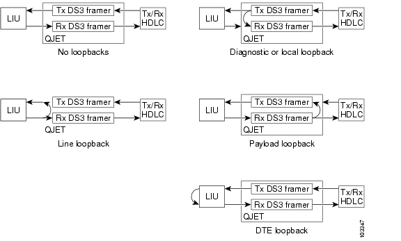
Table 4-8 provides examples of the loopback {dte | local | network {line | payload} command. The examples given are for interface 0 of a 6E3 line card in slot 2 of a Cisco 7304 router:
Figure 4-1 shows the data flow for three loopback configuration paths, including no loopback.
Figure 4-1 E3 Loopback Paths
Bit Error Rate Testing
The ratio of received bits on an interface that contain errors is called the bit error rate (BER). A bit error rate test (BERT) is used to check the BER. E3 bit error rate testing is used on the Cisco 7304 router to check communication between local and remote E3 ports. If traffic is not being transmitted or received on an E3 port, or if the quality of the line simply needs to be tested, E3 bit error rate testing can be used to test the port.
For information on performing bit error rate testing, refer to the Configuration Tasks section of the T3 Maintenance Data Link Messages on the Cisco 7304 Router documenat the following URL:
CLI-Controlled OIR
Line cards can be removed from the Cisco 7304 router without disrupting data flow by using the hw-module slot slot # stop/start command in EXEC mode. The hw-module slot slot # stop command will stop traffic, shut down all line card interfaces, and deactivate the line card. The hw-module slot slot # start command resets the line card, puts the line card back online and turns off the OIR LED.
Note
To remove and install an active line card in slot 2 proceed as follows:
Step 1
Router# hw-module slot 2 stopStep 2
When the OIR LED turns green, the line card in slot 2 has been deactivated and can be physically removed and replaced with a new line card (see the "Line Card Removal and Installation" section on page 3-3).
Step 3
Line Card Crash Recovery
The 6E3 line card automatically recovers from the following catastrophic errors:
•
•
•
•
•
If the 6E3 line card encounters more than five fatal errors within one hour, recovery will not be attempted and the line card will be deactivated. To reactivate the line card use the hw-module slot slot # start command, or physically remove and replace the line card.
The 6E3 line card crash history may be viewed by using the show diag slot command. The crash history is saved as long as the line card is physically present in the chassis. Physically removing the 6E3 line card from the chassis or performing a CLI-controlled OIR will clear the crash history.
The following messages are associated with line card recovery:
Error Message 00:00:06:% LC-3-RECOVERY: Line card (slot <x>) recovery in progressError Message 00:00:06:% LC-3-EXCESSERRORS: Errors seen on the line card (slot %d) exceeds the error thresholdWhen the 6E3 line card encounters any of the nonrecoverable errors listed below, the line card is deactivated and must be restarted by performing a CLI-controlled OIR or physically removing and installing the line card.
•
•
•
•
The following examples show nonrecoverable fatal error messages:
Error Message    00:00:06% SERIAL-0-DLL_OUTOFLOCK: E3 HW DLLS failed to lock in line
card at slot <x>
Error Message 00:00:06% SERIAL-0-860_BOOT_NOTOK: E3 Line card local processor at slot <x> failed to bootError Message 00:00:06% SERIAL-3-FW_CHECKSUM_FAILED: E3 line card in slot <x>, firmware integrity check failed (section <x>, expected checksum: <x>, calculated checksum: <x>)Error Message 00:00:06% ENVM-0-SHUTDOWN: Environmental Monitor initiated shutdown due to <voltage/temperature/power supply> in slot <x>Error Message 00:00:06% SERIAL-1-ALLOCFAIL: E3 (slot <x>) line card plugin structure allocation failureDSU Link Doesn't Work
Symptom
The link between the 6E3 line card and digitial link DSU (DL3100E) doesn't work when subrates have been configured. Pings don't go through.
Note
Conditions
This symptom is observed after you have reloaded a Cisco 7304, (when a 6-port E3 line card is connected to an external digital link DSU) and when the interface has the dsu bandwidth command enabled.
Workaround
Enter the shutdown command followed by the no shutdown command on the affected interface.
Router#conf t

Enter configuration commands, one per line. End with CNTL/Z.

Router(config)#int ser 5/0

Router(config-if)#shut

Router(config-if)#no shut
*Oct 20 21:39:34.331: %LINK-5-CHANGED: Interface Serial5/0, changed state to administratively down
Router(config-if)#
*Oct 20 21:39:34.331: %WS_ALARM-6-INFO: ASSERT INFO Se5/0 Physical Port Administrative State Down
*Oct 20 21:39:35.331: %LINEPROTO-5-UPDOWN: Line protocol on Interface Serial5/0, changed state to down
*Oct 20 21:39:37.263: %LINK-3-UPDOWN: Interface Serial5/0, changed state to down
*Oct 20 21:39:37.263: %WS_ALARM-6-INFO: CLEAR INFO Se5/0 Physical Port Administrative State Down
*Oct 20 21:39:37.263: %WS_ALARM-6-INFO: ASSERT MAJOR Se5/0 Physical Port Link Down
Router(config-if)#
Router(config-if)#
*Oct 20 21:39:41.895: %LINK-3-UPDOWN: Interface Serial5/0, changed state to up
*Oct 20 21:39:41.895: %WS_ALARM-6-INFO: CLEAR MAJOR Se5/0 Physical Port Link Down
*Oct 20 21:39:42.895: %LINEPROTO-5-UPDOWN: Line protocol on Interface Serial5/0, changed state to up
Router(config-if)#end
Router#
![]()
![]()
![]()
![]()
![]()
![]()
![]()
![]()
Posted: Wed Apr 21 20:36:51 PDT 2004
All contents are Copyright © 1992--2004 Cisco Systems, Inc. All rights reserved.
Important Notices and Privacy Statement.