|
|

Table Of Contents
Removing and Installing Line Cards
Line Card Removal and Installation
Cisco 7304—Removing and Installing a Line Card
Removing and Installing Line Cards
•
Installation Overview, page 3-1
•
•
Note
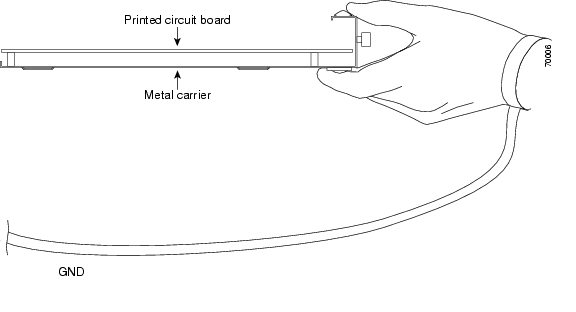
Handling Line Cards
Caution
Figure 3-1 Handling a Line Card
Online Insertion and Removal
The Cisco 7304 router supports online insertion and removal (OIR) of line cards; therefore, you do not have to power down the router when removing and replacing a 6E3 line card on a Cisco 7304 router. The Cisco 7304 router also supports CLI-controlled OIR, which allows active data traffic to complete before the active interfaces are shut down. For more information, see the "CLI-Controlled OIR" section on page 4-18.
Note
Note
Warnings and Cautions
Observe the following warnings and cautions when installing or removing line cards.
Caution
Caution
Warning
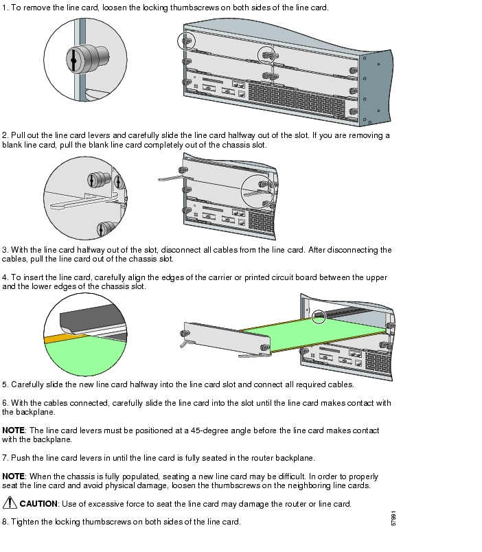
Line Card Removal and Installation
In this section, the illustrations that follow give step-by-step instructions on how to remove and install line cards. This section contains the following illustration:
•
Tip
Cisco 7304—Removing and Installing a Line Card
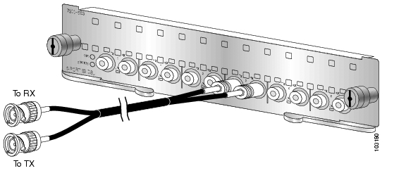
Connecting a SMB Cable
On a 6E3 line card, you can use six SMB cables (one for each E3 link).
Tip
Caution
Caution
Caution
To connect the SMB cables to the 6E3 line card, follow these steps:
Step 1
Step 2
a.
b.
Figure 3-2 Attaching SMB Cables to a 6E3 Line Card
![]()
![]()
![]()
![]()
![]()
![]()
![]()
![]()
Posted: Wed Apr 21 20:37:06 PDT 2004
All contents are Copyright © 1992--2004 Cisco Systems, Inc. All rights reserved.
Important Notices and Privacy Statement.