|
|

Table Of Contents
Interoperability Guidelines for 6E3 Line Card DSUs
Maintenance Data Link Messages
Line Card Slot Locations on the Supported Platform
Cisco 7304 Router Slot Numbering
Identifying Interface Addresses
Cisco 7304 Router Interface Addresses
Overview
This chapter describes the 6E3 line card and contains the following sections:
•
Features
•
•
•
•
Line Card Overview
The 6E3 line card provides a six port E3 single slot interface for the Cisco 7304 platform. This card provides direct customer IP access or network-to-network connections where copper E3 is the only service to a remote point of presence (POP).
The 6E3 line card:
•
•
•
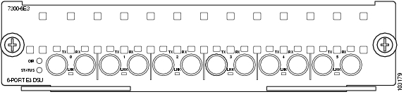
Figure 1-1 6-Port Clear Channel E3 Line Card
Features
The 6E3 line card provides the following features:
•
•
•
–
–
–
•
–
–
–
•
•
–
–
•
•
•
–
–
–
–
•
•
•
•
•
Interoperability Guidelines for 6E3 Line Card DSUs
The 6E3 line card supports several types of integrated data service units (DSUs). Table 1-1 lists the feature compatibilities of 6E3 line card DSUs.
Table 1-1 Feature Compatibilities of 6E3 Line Card DSUs
DL31002
Yes
Yes
Yes
No
Kentrox
Yes
Yes3
Yes2
No
1 MDL (maintenance data link)
2 See the "DSU Link Doesn't Work" section on page 4-20 for information about no ping response. Also see the release notes for Cisco IOS Release 12.2(20)S
3 The 6E3 line card supports scrambling and Kentrox subrate at the same time.
Maintenance Data Link Messages
E3 maintenance data link (MDL) messages are used to communicate identification information between local and remote ports. The type of information included in MDL messages includes the equipment identification code (EIC), location identification code (LIC), frame identification code (FIC), unit, Path Facility Identification (PFI), port number, and Generator Identification numbers. The values for each piece of MDL message identification can be defined only by a network administrator and are discussed in ANSI T1.107.
For information on transporting MDL messages between source and destination E3 ports on a Cisco 7304 router, refer to T3 Maintenance Data Link Messages on the Cisco 7304 Router at the following URL:
LEDs
The 6-port 6E3 line card has six LNK LEDs, one for each port, as well as one OIR LED and one STATUS LED. (See Figure 1-2.)
After system initialization, the STATUS LED goes on to indicate that power is received and that the 6E3 line card is enabled for operation.
The following conditions must all be met before the 6E3 line card is enabled:
•
•
•
If any one of these conditions is not met, or if the initialization fails, the STATUS LED does not go on.
Table 1-2 lists 6E3 line card LED colors and indications.
Figure 1-2 LEDs on the 6E3 Line Card
SMB Cables
The cables used to connect the 6E3 line card are presented in the following sections:
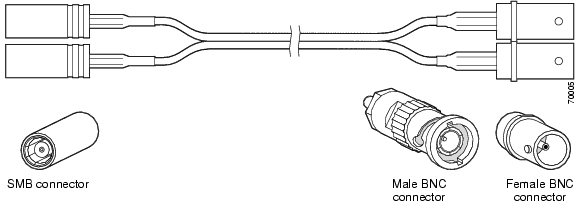
We recommend using six SMB cables. The cables are 10 feet (3.048 meters) long and have two female SMB connectors on one end, and two female or male bayonet coupling (BNC) connectors on the other end. Use the female SMB cable connectors to connect the local line card RX and TX ports. Use the BNC cable connectors to connect the line card RX and TX ports to other devices. See Figure 1-3.
Note
Figure 1-3 SMB Cables (SMB Terminates into BNC)
Note
If you use cables other than those ordered from Cisco, it is your responsibility to ensure that you have a compliant system that meets local EMC requirements. To order additional cables, use the product numbers: 2CBLE-SMB-BNC-M (male) and 2CBLE-SMB-BNC-F (female).
Note
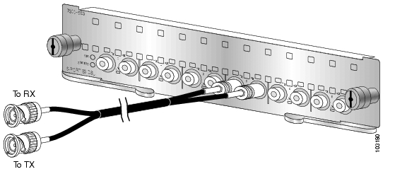
Figure 1-4 Connecting the SMB Cables
Note
Ordering Cables
You must order cables separately with the 6E3 line card when you order a Cisco 7304 router. Cables are not automatically included with the 6E3 line card. Be sure to specify the type of cable you want shipped with your card,
•
•
Building Your Own Cables
You can build your own cables for the 6E3 line card by using the cable components listed in Table 1-3. All three cables have an SMB connector at one end to connect to the 6E3 line card. The two SMB-to-BNC cables in Table 1-3 differ only in that one terminates in a male BNC connector, while the other terminates in a female BNC connector. You can use the back-to-back cable for directly connecting two closely-spaced 6E3 line cards back-to-back. These cables should be shielded and have SMB connectors on both ends.
Note
You can order the SMB-to-BNC cables from Cisco as product numbers 2CBLE-SMB-BNC-M (male) or 2CBLE-SMB-BNC-F (female) BNC terminations, respectively. Cisco does not sell the SMB-to-SMB cable.
Caution
E3 systems are designed for cable lengths of 450 feet (137 meters) between the transmitter and the DSX-3 demarcation point where the standard pulse mask must be met. From the DSX-3 point, another run of 450 feet (137 meters) is allowed to the receiver, making a total of 900 feet (274 meters) between transmitter and receiver. This limitation is due to signal attenuation in the cable.
Although the American National Standards Institute (ANSI) standard T1.404-1994 stipulates the Western Electric or equivalent 728A SMB cable, it has been replaced by the Lucent (formerly AT&T) 734A cable. Cisco tested more than 900 feet (274 meters) of 734A SMB cable from transmitter to receiver including the SMB-to-BNC adapter cables to verify high signal attenuation.
Table 1-4 lists some approximate attenuation values from the ANSI standard, and shows the RG-179 coaxial cable attenuation. RG-179coaxial cable has a much higher attenuation, so take this information into account if you plan long runs of RG-179 cable.
Table 1-4 ANSI Standard Cable-Attenuation Values
Frequency
100 ft (30 meters)
DSX-3 Point1 MHz
0.27
1.2
2.4
3.0
10 MHz
0.80
3.6
7.2
5.3
50 MHz
1.82
8.2
16.4
8.5
100 MHz
2.64
11.9
23.8
10.0
1 dB = decibels
Management Information Base
Management Information Base (MIB) attributes are readable and writable across the Integrated Local Management Interface (ILMI) through use of the Simple Network Management Protocol (SNMP). The 6-port 6E3 line card supports the DS3 interface MIB (RFC 1407). For more MIB support information, see the Cisco 7304 Router MIB Overview at the following URL:
http://www.cisco.com/univercd/cc/td/doc/product/core/cis7300/7304mibs/7300mib1.htm
Line Card Slot Locations on the Supported Platform
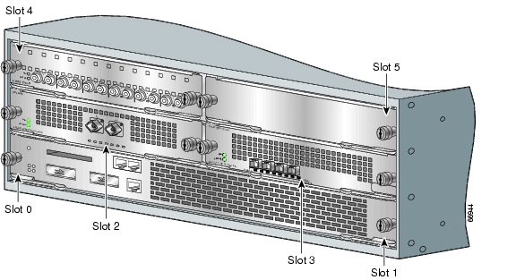
This section discusses line card slot locations on the supported platform. Figure 1-5 summarizes slot location conventions on the Cisco 7304 router.
Cisco 7304 Router Slot Numbering
Figure 1-5 shows a Cisco 7304 with the network services engine (NSE) installed in slots 0 and 1 and line cards installed in slots 2 through 4. In the Cisco 7304, slot 0 is in the lower left position, and slot 5 is in the upper right position.
Figure 1-5 Slots in the Cisco 7304 Router
Identifying Interface Addresses
This section describes how to identify interface addresses for the 6E3 line card in the Cisco 7304 router. Interface addresses specify the actual physical location of each interface on a router or switch.
Interfaces on the 6E3 line card installed in a router maintain the same address regardless of whether other line cards are installed or removed. However, when you move a line card to a different slot, the first number in the interface address changes to reflect the new slot number.
Table 1-5 explains how to identify interface addresses.
Table 1-5 Identifying Interface Addresses
Cisco 7304 router
Slot-number/interface-port-number
Slot—2 through 51
Interface port—0 through 54/0
1 Slot 0 and slot 1 are reserved for the dual-width network services engine (NSE).
Cisco 7304 Router Interface Addresses
This section describes how to identify the interface addresses used for the 6E3 line card in the Cisco 7304 router. The interface address is composed of a two-part number in the format slot-number/interface-port-number. See Table 1-5 for the interface address format.
In the Cisco 7304 router, slots are numbered from the lower left to the upper right, beginning with slot 0 and continuing through slot 5. (Slot 0 and slot 1 are reserved for the NSE.)
The interface address of the interfaces on a 6-port 6E3 line card in slot 2 are 2/0 through 2/5 (slot 2 and interfaces 0 through 5). If the 6E3 line card was in slot 4, these same interfaces would be numbered 4/0 through 4/5 (slot 4 and interfaces 0 through 5).
![]()
![]()
![]()
![]()
![]()
![]()
![]()
![]()
Posted: Wed Apr 21 20:38:45 PDT 2004
All contents are Copyright © 1992--2004 Cisco Systems, Inc. All rights reserved.
Important Notices and Privacy Statement.