|
|

Table Of Contents
Overview: Cisco 12000 Series Router Shared Port Adapters
Checking Hardware and Software Compatibility
2-Port and 4-Port T3/E3 Serial SPA Overview
2-Port and 4-Port Clear Channel T3/E3 SPA LEDs
2-Port and 4-Port Clear Channel T3/E3 SPA Interface Specifications
2-Port and 4-Port Clear Channel T3/E3 SPA Cables and Connectors
2-Port and 4-Port Channelized T3 to DS0 SPA Overview
2-Port and 4-Port Channelized T3 SPA LEDs
2-Port and 4-Port Channelized T3 SPA Interface Specifications
2-Port and 4-Port Channelized T3 SPA Cables and Connectors
8-Port Channelized T1/E1 SPA Overview
8-Port Channelized T1/E1 SPA LEDs
8-Port Channelized T1/E1 SPA Interface Specifications
8-Port Channelized T1/E1 SPA Cables, Connectors, and Pinouts
8-Port Fast Ethernet SPA Overview
8-Port FastEthernet SPA Cables, Connectors, and Pinouts
1-Port 10-Gigabit Ethernet SPA Overview
1-Port 10-Gigabit Ethernet SPA LEDs
1-Port 10-Gigabit Ethernet SPA XFP Optical Transceiver Modules, Connectors, and Cables
XFP Port Cabling Specifications
2-Port Gigabit Ethernet SPA Overview
2-Port Gigabit Ethernet SPA LEDs
5-Port Gigabit Ethernet SPA Overview
5-Port Gigabit Ethernet SPA LEDs
5-Port Gigabit Ethernet SPA Cables and Connectors
10-Port Gigabit Ethernet SPA Overview
10-Port Gigabit Ethernet SPA LEDs
10-Port Gigabit Ethernet SPA Cables and Connectors
1-Port Channelized STM-1/OC-3 SPA Overview
1-Port Channelized STM-1/OC-3 SPA LEDs
1-Port Channelized STM-1/OC-3 SPA Interface Specifications
1-Port Channelized STM-1/OC-3 SPA Cables and Connectors
1-Port OC-48c/STM-16 POS SPA Overview
1-Port OC-48c/STM-16 POS SPA LEDs
1-Port OC-48c/STM-16 POS SPA Interface Specifications
1-Port OC-48c/STM-16 POS SPA Optical Transceiver Modules, Connectors, and Cables
1-Port OC-192c/STM-64 POS SPA Overview
1-Port OC-192c/STM-64 POS/RPR SPA LEDs
1-Port OC-192c/STM-64 POS/RPR SPA Interface Specifications
1-Port OC-192c/STM-64 POS/RPR SPA Fixed Optical Transceiver, 40-Pin Connector, and Cables
1-Port OC-192c/STM-64 POS RPR XFP SPA Overview
1-Port OC-192c/STM-64 POS/RPR XFP SPA LEDs
1-Port OC-192c/STM-64 POS/RPR XFP SPA Interface Specifications
1-Port OC-192c/STM-64 POS/RPR XFP SPA Optical Transceiver Modules, Connectors, and Cables
2-Port OC-48 POS RPR SPA Overview
2-Port OC48-POS/RPR SPA Interface Specifications
2-Port OC48-POS/RPR SPA Cables, Optical Transceiver Modules, and Connectors
Overview: Cisco 12000 Series Router Shared Port Adapters
Release 12.0(32)SY1, OL-8831-01, Rev. G6, July 19, 2007
This chapter describes the shared port adapters (SPAs) that are supported on the Cisco 12000 Series Router and contains the following sections:
•
2-Port and 4-Port T3/E3 Serial SPA Overview
•
•
•
•
•
•
•
•
•
•
•
•
SPA Summary
Table 2-1 shows the summary descriptions of the SPAs that are supported on the Cisco 12000 Series Router.
Checking Hardware and Software Compatibility
To check the minimum software requirements of Cisco IOS software with the hardware installed on your router, Cisco maintains the Software Advisor tool on Cisco.com. This tool does not verify whether SIPs or SPAs within a system are compatible, but it does provide the minimum Cisco IOS requirements for individual hardware modules or components.
Note
To access Software Advisor, click Login at Cisco.com, type "Software Advisor" in the SEARCH box, and click GO. Click the link for the Software Advisor tool.
Choose a product family or enter a specific product number to search for the minimum supported software release needed for your hardware.
Bandwidth Oversubscription
Oversubscribing the bandwidth limit recommendations of a router can result in decreased or degraded performance. For this reason, it is important to determine the amount of bandwidth used by the SPAs on the router and verify that the total bandwidth used by all SPAs does not exceed the recommended bandwidth limit of the router.
Table 2-2 provides information about the bandwidth for each port (per-port bandwidth) on a SPA, as well as the cumulative bandwidth (total bandwidth) for all ports available on the SPA.
Table 2-2 SPA Bandwidth Capacity
SPA
of Ports2-Port Channelized T3 SPA
44.736 Mbps
2
89.47 Mbps
4-Port Channelized T3 SPA
44.736 Mbps
4
178.94 Mbps
2-Port Clear Channel T3/E3 SPA
44.736 Mbps (T3)
34.368 Mbps (E3)2
89.47 Mbps (T3)
68.74 Mbps (E3)4-Port Clear Channel T3/E3 SPA
44.736 Mbps (T3)
34.368 Mbps (E3)4
178.94 Mbps (T3)
137.47 Mbps (E3)8-Port Channelized T1/E1 SPA
1.544 Mbps (T1)
2.048 Mbps (E1)
8
12.35 Mbps (T1)
16.38 Mbps (E1)
1-Port 10-Gigabit Ethernet SPA
10 Gbps
1
10 Gbps
2-Port Gigabit Ethernet SPA
1 Gbps
2
2 Gbps
5-Port Gigabit Ethernet SPA
1 Gbps
5
5 Gbps
10-Port Gigabit Ethernet SPA
1 Gbps
10
10 Gbps
1-Port OC-48c/STM-16 POS SPA
2.488 Gbps
1
2.488 Gbps
1-Port OC-192c/STM-64 POS SPA
9.953 Gbps
1
9.953 Gbps
2-Port OC48-POS/RPR SPA
2.488 Gbps
2
4.976 Gbps
2-Port OC-3c/STM-1 and OC-12c/STM-4 POS SPA
155.52 Mbps or
622.08 Mbps
2
1.244 Gbps
4-Port OC-3c/STM-1 and OC-12c/STM-4 POS SPA
155.52 Mbps or
622.08 Mbps
4
2.488 Gbps
8-Port OC-3c/STM-1 and OC-12c/STM-4 POS SPA
155.52 Mbps or
622.08 Mbps
8
5 Gbps1
4-Port OC-3c/STM-1 POS SPA
155.52 Mbps
4
622.08 Mbps
8-Port OC-3c/STM-1 POS SPA
155.52 Mbps
8
1.244 Gbps
1 Total bandwidth value assumes eight OC-12c/STM-4 optics modules.
2-Port and 4-Port T3/E3 Serial SPA Overview
The following sections describe the 2-Port and 4-Port Clear Channel T3/E3 SPA:
•
•
•
2-Port and 4-Port Clear Channel T3/E3 SPA LEDs
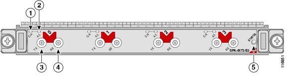
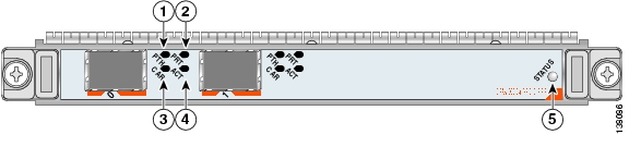
The 2-Port and 4-Port Clear Channel T3/E3 SPA has three types of LEDs. There are two LEDs for each port on the SPA, and one STATUS LED. Figure 2-1 shows an example of these LEDs on a 4-Port Clear Channel T3/E3 SPA.
Figure 2-1 4-Port Clear Channel T3/E3 SPA Faceplate
C/A (Carrier/Alarm) LED
RX (Receive) connector
A/L (Active Loopback) LED
STATUS LED
TX (Transmit) connector
The 2-Port and 4-Port Clear Channel T3/E3 SPA LEDs are described in Table 2-3.
2-Port and 4-Port Clear Channel T3/E3 SPA Interface Specifications
The framer processes incoming and outgoing T3 (cbit, m13/m23, and unframe) and E3 (g751, g832, and unframe) frames. The framer operates at T3/E3 line rates (44.2/34.0 Mbps) depending on the mode in which it is configured.
Packet data is transported with a user-configurable encapsulation (such as Point-to-Point Protocol [PPP] or High-Level Data Link Control [HDLC]), and is mapped to T3 and E3 frames. The encapsulations add transport overhead to the packet of data frames before transporting, and are stripped when a packet is transported to the far end.
The T3/E3 SPA interface is compliant with ANSI and Telco standards. The interface also provides support for Management Information Base (MIB) RFC 2496 and T1.231.
2-Port and 4-Port Clear Channel T3/E3 SPA Cables and Connectors
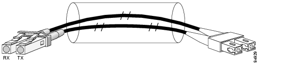
The interface connectors on the 2-Port and 4-Port Clear Channel T3/E3 SPA are 75-ohm RG-59 coaxial Siemax types, with one connector and cable for transmit (TX) and one for receive (RX).
The following cables can be used with the 2-Port and 4-Port Clear Channel T3/E3 SPA. The cables have BNC connectors on one end and the Siemax connectors on the other.
•
•
•
Note
Figure 2-1 shows the connectors on the 4-Port Clear Channel T3/E3 SPA, and Table 2-4 describes the signal descriptions for these connectors.
2-Port and 4-Port Channelized T3 to DS0 SPA Overview
The following sections describe the 2-Port and 4-Port Channelized T3 SPA:
•
•
•
2-Port and 4-Port Channelized T3 SPA LEDs
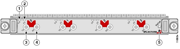
The 2-Port and 4-Port Channelized T3 SPA has three types of LEDs. There are two LEDs for each port on the SPA, and one STATUS LED. Figure 2-2 shows an example of these LEDs on a 4-Port Channelized T3 SPA.
Figure 2-2 4-Port Channelized T3 SPA Faceplate
C/A (Carrier/Alarm) LED
RX (Receive) connector
A/L (Active Loopback) LED
STATUS LED
TX (Transmit) connector
The 2-Port and 4-Port Channelized T3 SPA LEDs are described in Table 2-5.
2-Port and 4-Port Channelized T3 SPA Interface Specifications
The framer processes incoming and outgoing T3 frames (cbit, m13/m23, and unframe). The framer operates at T3 line rates (44.2 Mbps).
Packet data is transported with a user-configurable encapsulation (such as Point-to-Point Protocol [PPP] or High-Level Data Link Control [HDLC]), and is mapped to T3 frames. The encapsulations add transport overhead to the packet of data frames before transporting, and are stripped when a packet is transported to the far end.
The T3 SPA interface is compliant with ANSI and Telco standards. The interface also provides support for Management Information Base (MIB) RFC 2495, RFC 2496, and T1.231.
2-Port and 4-Port Channelized T3 SPA Cables and Connectors
The interface connectors on the 2-Port and 4-Port Channelized T3 SPA are 75-ohm coaxial Siemax types, with one connector and cable for transmit (TX) and one for receive (RX).
The following cables can be used with the 2-Port and 4-Port Channelized T3 SPA. The cables have BNC connectors on one end and the Siemax connectors on the other.
•
•
•
Note
Figure 2-2 shows the Siemax connectors on the 2-Port and 4-Port Channelized T3 SPA, and Table 2-6 provides the signal descriptions for these connectors.
8-Port Channelized T1/E1 SPA Overview
Note
The following sections describe the 8-Port Channelized T1/E1 SPA:
•
•
•
8-Port Channelized T1/E1 SPA LEDs
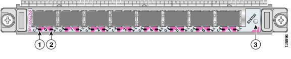
The 8-Port Channelized T1/E1 SPA has three types of LEDs. There are two LEDs for each port on the SPA, and one STATUS LED as shown in Figure 2-3.
Figure 2-3 8-Port Channelized T1/E1 SPA Faceplate
The 8-Port Channelized T1/E1 SPA LEDs are described in Table 2-7.
8-Port Channelized T1/E1 SPA Interface Specifications
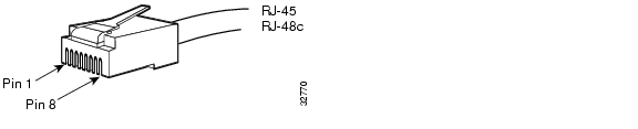
The E1 interface on the 8-Port Channelized T1/E1 SPA uses RJ-48c receptacles for E1 (120-Ohm) cables with RJ-45 connectors. You can use all ports simultaneously. Each E1 connection supports interfaces that meet G.703 standards. The RJ-45 connection does not require an external transceiver. The E1 ports are E1 interfaces that use 120-ohm unshielded twisted pair (UTP) cables.
8-Port Channelized T1/E1 SPA Cables, Connectors, and Pinouts
Figure 2-4 shows an RJ-45 connector.
Note
Figure 2-4 RJ-45 Connector
Table 2-8 describes the signals and connector pinouts for RJ-45 cable connectors.
8-Port Fast Ethernet SPA Overview
The following sections describe the 8-Port FastEthernet SPA:
•
•
8-Port FastEthernet SPA LEDs
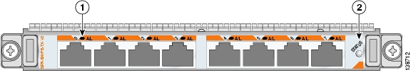
The 8-Port FastEthernet SPA has two types of LEDs: an A/L LED for each individual port and a STATUS LED for the SPA, as shown in Figure 2-5.
Figure 2-5 8-Port FastEthernet SPA Faceplate
Table 2-9 describes the 8-Port FastEthernet SPA LEDs.
Table 2-9 8-Port FastEthernet SPA LEDs
Port Number
A/L (0, 1, 2, 3, 4, 5, 6 or 7)1Off
Off
Port is not enabled.
Green
On
Port is enabled and the link is up.
Amber
On
Port is enabled and the link is down.
STATUS
Off
Off
SPA power is off.
Green
On
SPA is ready and operational.
Amber
On
SPA power is on and good, and the SPA is being configured.
1 In this case, port number refers to the numbered LEDs on the 8-Port FastEthernet SPA (0, 1, 2, 3, 4, 5, 6 or 7). Each LED number on the 8-Port FastEthernet SPA references a port on the SPA.
8-Port FastEthernet SPA Cables, Connectors, and Pinouts
The interface connectors on the 8-Port FastEthernet SPA are eight individual RJ-45 receptacles. You can use all eight interface connectors simultaneously. Each connection supports IEEE 802.3 and Ethernet 10/100BASE-T interfaces compliant with appropriate standards. Cisco Systems does not supply Category 5 unshielded twisted-pair (UTP) RJ-45 cables; these cables are available commercially.
Figure 2-6 shows the RJ-45 connector.
Figure 2-6 RJ-45 Connections, Plug, and Receptacle
Table 2-10 lists the pinouts and signals for the RJ-45 connector.
Table 2-10 RJ-45 Connector Pinout
1
Transmit data + (TxD+)
2
TxD-
3
Receive data + (RxD+)
4
Reserved
5
Reserved
6
RxD-
7
Reserved
8
Reserved
Note
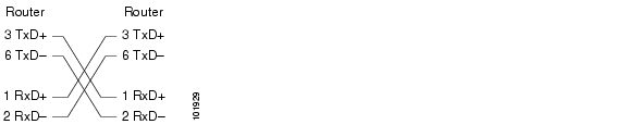
The 8-Port FastEthernet SPA supports automatic MDI/MDIX crossover at all speeds of operation allowing the SPA to work with straight-through and crossover Ethernet cables. Depending on your RJ-45 interface cabling requirements, use the pinouts in Figure 2-7 and Figure 2-8.
Figure 2-7 Straight-Through Cable Pinout, RJ-45 Connection to a Hub or Repeater
Figure 2-8 Crossover Cable Pinout, RJ-45 Connections Between Routers
1-Port 10-Gigabit Ethernet SPA Overview
The following sections describe the 1-Port 10-Gigabit Ethernet SPA:
•
•
1-Port 10-Gigabit Ethernet SPA LEDs
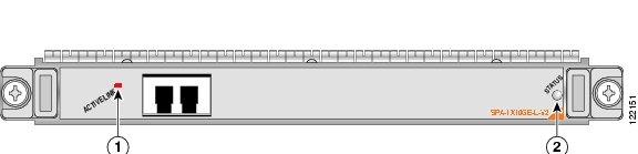
The 1-Port 10-Gigabit Ethernet SPA has two LEDs, an ACTIVE/LINK LED for the port and a STATUS LED, as shown in Figure 2-9.
Figure 2-9 1-Port 10-Gigabit Ethernet SPA Faceplate
Table 2-11 describes the 1-Port 10-Gigabit Ethernet SPA LEDs.
1-Port 10-Gigabit Ethernet SPA XFP Optical Transceiver Modules, Connectors, and Cables
The 1-Port 10-Gigabit Ethernet SPA supports the following types of optical transceiver modules:
•
•
•
Cisco Systems qualifies the optics that are approved for use with its SPAs. As of the above listed small form-factor pluggable (XFPs) are the only optical transceiver modules qualified for use.
Use a single-mode optical fiber that has a modal-field diameter of 8.7 ±0.5 microns (nominal diameter is approximately 10/125 microns) to connect your router to a network.
Figure 2-10 shows the cable type for use with the XFP optical transceiver module on the 1-Port 10-Gigabit Ethernet SPA.
Figure 2-10 LC-Type Cable for the XFP Optical Transceiver Modules
Note
XFP Connections
The XFP-10GLR-OC192SR, XFP-10GER-OC192IR, and XFP-10GZR-OC192LR XFPs include an optical transmitter and receiver pair integrated with Clock and Data Recovery (CDR) integrated circuits. The XFPs provide high-speed serial links at the following rates: 9.95 Gbps (OC-192) and 10.3125 Gbps (10 Gigabit Ethernet) on single mode fibers. The transmit side recovers and retimes the 10 Gbps serial data and passes it to a laser driver. The laser driver biases and modulates a 1310 nm or 1550 nm laser, enabling data transmission over SMF through an LC connector. The receive side recovers and retimes the 10 Gbps optical data stream from a photo detector trans impedance amplifier and passes it to an output driver.
See the label on the XFP for technology type and model.
XFP dimensions are:
•
•
•
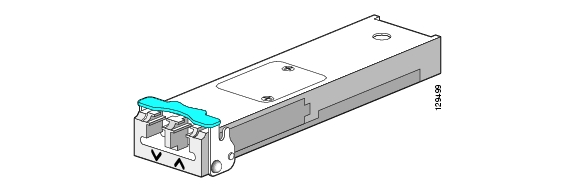
The XFP temperature range is 0°C to 70°C. For a picture of an XFP, see Figure 2-11.
Figure 2-11 XFP Illustration
XFP Port Cabling Specifications
Table 2-12 XFP Port Cabling Specifications
XFP-10GLR-OC192SR
1310 nm
SMF
XFP-10GER-OC192IR
1550 nm
SMF
XFP-10GZR-OC192LR
1550 nm
SMF
2-Port Gigabit Ethernet SPA Overview
The following sections describe the 2-Port Gigabit Ethernet SPA:
•
•
2-Port Gigabit Ethernet SPA LEDs
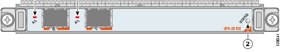
The 2-Port Gigabit Ethernet SPA has two types of LEDs: an A/L LED for each port and a STATUS LED, as shown in Figure 2-12.
Figure 2-12 2-Port Gigabit Ethernet SPA Faceplate
Table 2-13 describes the 2-Port Gigabit Ethernet SPA LEDs.
2-Port Gigabit Ethernet SPA Cables and Connectors
The interface connectors on the 2-Port Gigabit Ethernet SPA are two individual fiber-optic receivers that support SFP modules. Each port can send and receive traffic using the optical fiber connections.
SFP Module Connections
The small form-factor pluggable (SFP) module is an input/output (I/O) device that plugs into the Gigabit Ethernet ports on the 2-Port Gigabit Ethernet SPA, linking the port with a fiber-optic network.
Note
SFP modules exist for technologies other than Gigabit Ethernet and for products other than the 2-Port Gigabit Ethernet SPA. However, the information in this document pertains only to SFP modules that plug into the 2-Port Gigabit Ethernet SPA ports.The SFP module has a receiver port (RX) and a transmitter port (TX) that compose one optical interface. Table 2-14 and Table 2-15 provide SFP module information and specifications.
SFP-GE-S Modules
The 1000BASE-SX (short wavelength) module operates on standard multimode fiber-optic link spans of up to 500 m on 50/125um MMF and 300 m on 62.5/125um MMF.
SFP-GE-L Modules
The 1000BASE-LX/LH (long wavelength/long haul) module interfaces fully comply with the
IEEE 802.3z 1000BASE-LX standard. However, their higher optical quality allows them to reach 6.2 miles (10 km) over single-mode fiber (SMF) versus the 3.1 miles (5 km) specified in the standard.SFP-GE-Z Modules
The 1000BASE-ZX (extended wavelength) module operates on ordinary single-mode fiber-optic link spans of up to 49.7 miles (80 km). Link spans of up to 62.1 miles (100 km) are possible using premium single-mode fiber or dispersion-shifted single-mode fiber (premium single-mode fiber has a lower attenuation per unit length than ordinary single-mode fiber; dispersion-shifted single-mode fiber has both lower attenuation and less dispersion).
The 1000BASE-ZX module must be coupled to single-mode fiber-optic cable, which is the type of cable typically used in long-haul telecommunications applications. The 1000BASE-ZX module will not operate correctly when coupled to multimode fiber, and it is not intended to be used in environments where multimode fiber is frequently used (for example, building backbones, or horizontal cabling).
The 1000BASE-ZX module is intended to be used as a Physical Medium Dependent (PMD) component for Gigabit Ethernet interfaces found on various switch and router products. It operates at a signaling rate of 1250 Mbaud, transmitting and receiving 8B/10B encoded data.
When shorter lengths of single-mode fiber are used, it may be necessary to insert an in-line optical attenuator in the link to avoid overloading the receiver.
•
•
SFP-GE-T Modules
The SFP-GE-T (1000BASE-T copper SFP module) provides full-duplex Gigabit Ethernet connectivity to high-end workstations and between wiring closets over an existing copper network infrastructure. The SFP-GE-T maximum cabling distance is 328 feet (100 m).
SFP Module Cabling and Connection Equipment
Table 2-16 provides cabling specifications for the SFP modules that can be installed on the 2-Port Gigabit Ethernet SPA. Note that all SFP ports have LC-type connectors.
The minimum cable distance for the SFP-GE-S is 6.5 feet (2 m), and the minimum link distance for the SFP-GE-Z is 6.2 miles (10 km) with an 8-dB attenuator installed at each end of the link. Without attenuators, the minimum link distance for the SFP-GE-Z is 24.9 miles (40 km).
Table 2-16 SFP Module Port Cabling Specifications
Cable DistanceSFP-GE-S
850
MMF1
62.5
160
722 ft (220 m)
62.5
200
984 ft (300 m)
50.0
400
1640 ft (500 m)
50.0
500
1804 ft (550 m)
SFP-GE-L
1300
MMF2 and SMF
62.5
500
1804 ft (550 m)
50.0
400
1804 ft (550 m)
50.0
500
1804 ft (550 m)
9/10
—
6.2 miles (10 km)
SFP-GE-Z
1550
SMF
9/10
—
49.7 miles (80 km)
SMF3
8
—
62.1 miles (100 km)
SFP-GE-T
N/A
Copper
N/A
N/A
328 ft. (100 m)
1 Multimode fiber (MMF) only.
2 A mode-conditioning patch cord is required.
When using the SFP-GE-L with 62.5-micron diameter MMF, you must install a mode-conditioning patch cord between the SFP module and the MMF cable on both the transmit and the receive ends of the link when link distances are greater than 984 ft (300 m).
We do not recommend using the SFP-GE-L and MMF with no patch cord for very short link distance (tens of meters). The result could be an elevated bit error rate (BER).3 Dispersion-shifted single-mode fiber-optic cable.
Note
5-Port Gigabit Ethernet SPA Overview
The following sections describe the 5-Port Gigabit Ethernet SPA:
•
•
5-Port Gigabit Ethernet SPA LEDs
The 5-Port Gigabit Ethernet SPA has two types of LEDs: an A/L LED for each individual port and a STATUS LED for the SPA, as shown in Figure 2-13.
Figure 2-13 5-Port Gigabit Ethernet SPA Faceplate
Table 2-17 describes the 5-Port Gigabit Ethernet SPA LEDs.
5-Port Gigabit Ethernet SPA Cables and Connectors
The 5-Port Gigabit Ethernet SPA has five electrical connectors that support SFP modules. Each port can send and receive traffic using cabling appropriate for the SFP module inserted.
SFP Module Connections
The small form-factor pluggable (SFP) module is an input/output (I/O) device that plugs into the Gigabit Ethernet ports on the 5-Port Gigabit Ethernet SPA, linking the port with a fiber-optic network.
Note
SFP modules exist for technologies other than Gigabit Ethernet and for products other than the 5-Port Gigabit Ethernet SPA. However, the information in this document pertains only to SFP modules that plug into the 5-Port Gigabit Ethernet SPA ports.The SFP module has a receiver port (RX) and a transmitter port (TX) that compose one optical interface. Table 2-18 and Table 2-19 provide SFP module information and specifications.
SFP-GE-S Modules
The 1000BASE-SX (short-wavelength) module operates on standard multimode fiber-optic link spans of up to 500 m on 50/125um multimode fiber (MMF) and 300 m on 62.5/125um MMF.
SFP-GE-L Modules
The 1000BASE-LX/LH (long-wavelength/long-haul) module interfaces fully comply with the
IEEE 802.3z 1000BASE-LX standard. However, their higher optical quality allows them to reach 6.2 miles (10 km) over single-mode fiber (SMF) versus the 3.1 miles (5 km) specified in the standard.SFP-GE-Z Modules
The 1000BASE-ZX (extended wavelength) module operates on ordinary single-mode fiber-optic link spans of up to 49.7 miles (80 km). Link spans of up to 62.1 miles (100 km) are possible using premium single-mode fiber or dispersion-shifted single-mode fiber. (Premium single-mode fiber has a lower attenuation per unit length than ordinary single-mode fiber; dispersion-shifted single-mode fiber has both lower attenuation and less dispersion.)
The 1000BASE-ZX module must be coupled to single-mode fiber-optic cable, which is the type of cable typically used in long-haul telecommunications applications. The 1000BASE-ZX module does not operate correctly when coupled to multimode fiber, and it is not intended to be used in environments in which multimode fiber is frequently used (for example, building backbones or horizontal cabling).
The 1000BASE-ZX module is intended to be used as a Physical Medium Dependent (PMD) component for Gigabit Ethernet interfaces found on various switch and router products. It operates at a signaling rate of 1250 Mbaud, transmitting and receiving 8B/10B encoded data.
When shorter lengths of single-mode fiber are used, it may be necessary to insert an inline optical attenuator in the link to avoid overloading the receiver. Use the following guidelines:
•
•
SFP-GE-T Modules
The SFP-GE-T (1000BASE-T copper SFP module) provides full-duplex Gigabit Ethernet connectivity to high-end workstations and between wiring closets over an existing copper network infrastructure. The SFP-GE-T maximum cabling distance is 328 feet (100 m).
SFP Module Cabling and Connection Equipment
Table 2-20 provides cabling specifications for the SFP modules that can be installed on the 5-Port Gigabit Ethernet SPA. Note that all SFP ports have LC-type connectors.
The minimum cable distance for the SFP-GE-S is 6.5 feet (2 m), and the minimum link distance for the SFP-GE-Z is 6.2 miles (10 km) with an 8-dB attenuator installed at each end of the link. Without attenuators, the minimum link distance for the SFP-GE-Z is 24.9 miles (40 km).
Table 2-20 SFP Module Port Cabling Specifications
Cable DistanceSFP-GE-S
850
MMF1
62.5
160
722 ft (220 m)
62.5
200
984 ft (300 m)
50.0
400
1640 ft (500 m)
50.0
500
1804 ft (550 m)
SFP-GE-L
1300
MMF2 and SMF
62.5
500
1804 ft (550 m)
50.0
400
1804 ft (550 m)
50.0
500
1804 ft (550 m)
9/10
—
6.2 miles (10 km)
SFP-GE-Z
1550
SMF
9/10
—
49.7 miles (80 km)
SMF3
8
—
62.1 miles (100 km)
SFP-GE-T
N/A
Copper
N/A
N/A
328 ft. (100 m)
1 Multimode fiber (MMF) only.
2 A mode-conditioning patch cord is required.
When using the SFP-GE-L with 62.5-micron diameter MMF, you must install a mode-conditioning patch cord between the SFP module and the MMF cable on both the transmit and the receive ends of the link when link distances are greater than 984 ft (300 m).
We do not recommend using the SFP-GE-L and MMF with no patch cord for very short link distance (tens of meters). The result could be an elevated bit error rate (BER).3 Dispersion-shifted single-mode fiber-optic cable.
Note
10-Port Gigabit Ethernet SPA Overview
The following sections describe the 10-Port Gigabit Ethernet SPA:
•
•
10-Port Gigabit Ethernet SPA LEDs
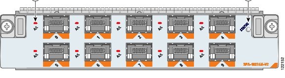
The 10-Port Gigabit Ethernet SPA has two types of LEDs: an A/L LED for the port and a STATUS LED, as shown in Figure 2-14.
Figure 2-14 10-Port Gigabit Ethernet SPA Faceplate
Table 2-21 describes the 10-Port Gigabit Ethernet SPA LEDs.
10-Port Gigabit Ethernet SPA Cables and Connectors
The 10-Port Gigabit Ethernet SPA has ten electrical connectors which support SFPs modules. Each port can send and receive traffic using cabling appropriate for the SFP module inserted.
SFP Module Connections
The small form-factor pluggable (SFP) module is an input/output (I/O) device that plugs into the Gigabit Ethernet optical slots on the 10-Port Gigabit Ethernet SPA, linking the port with a 1000BASE-X fiber-optic network.
Note
SFP modules exist for technologies other than Gigabit Ethernet and for products other than the 10-Port Gigabit Ethernet SPA. However, the information in this document pertains only to SFP modules that plug into the 10-Port Gigabit Ethernet SPA ports.The SFP module has a receiver port (RX) and a transmitter port (TX) that compose one optical interface. Table 2-22 and Table 2-23 provide SFP information and specifications.
SFP-GE-S Modules
The 1000BASE-SX (short wavelength) module operates on standard multimode fiber-optic link spans of up to 500 m on 50/125um MMF and 300 m on 62.5/125um MMF.
SFP-GE-L Modules
The 1000BASE-LX/LH (long wavelength/long haul) module interfaces fully comply with the
IEEE 802.3z 1000BASE-LX standard. However, their higher optical quality allows them to reach 6.2 miles (10 km) over single-mode fiber (SMF) versus the 3.1 miles (5 km) specified in the standard.SFP-GE-Z Modules
The 1000BASE-ZX (extended wavelength) module operates on ordinary single-mode fiber-optic link spans of up to 49.7 miles (80 km). Link spans of up to 62.1 miles (100 km) are possible using premium single-mode fiber or dispersion-shifted single-mode fiber (premium single-mode fiber has a lower attenuation per unit length than ordinary single-mode fiber; dispersion-shifted single-mode fiber has both lower attenuation and less dispersion).
The 1000BASE-ZX module must be coupled to single-mode fiber-optic cable, which is the type of cable typically used in long-haul telecommunications applications. The 1000BASE-ZX module will not operate correctly when coupled to multimode fiber, and it is not intended to be used in environments where multimode fiber is frequently used (for example, building backbones, or horizontal cabling).
The 1000BASE-ZX module is intended to be used as a Physical Medium Dependent (PMD) component for Gigabit Ethernet interfaces found on various switch and router products. It operates at a signaling rate of 1250 Mbaud, transmitting and receiving 8B/10B encoded data.
When shorter lengths of single-mode fiber are used, it may be necessary to insert an in-line optical attenuator in the link to avoid overloading the receiver. Use the following guidelines:
•
•
SFP-GE-T Modules
The SFP-GE-T (1000BASE-T copper SFP module) provides full-duplex Gigabit Ethernet connectivity to high-end workstations and between wiring closets over an existing copper network infrastructure. The SFP-GE-T maximum cabling distance is 328 feet (100 m).
SFP Module Cabling and Connection Equipment
Table 2-24 provides cabling specifications for the SFP modules that can be installed on the 10-Port Gigabit Ethernet SPA. Note that all SFP ports have LC-type connectors.
The minimum cable distance for the SFP-GE-S is 6.5 feet (2 m), and the minimum link distance for the SFP-GE-Z is 6.2 miles (10 km) with an 8-dB attenuator installed at each end of the link. Without attenuators, the minimum link distance for the SFP-GE-Z is 24.9 miles (40 km).
Table 2-24 SFP Module Port Cabling Specifications
Cable DistanceSFP-GE-S
850
MMF1
62.5
160
722 ft (220 m)
62.5
200
984 ft (300 m)
50.0
400
1640 ft (500 m)
50.0
500
1804 ft (550 m)
SFP-GE-L
1300
MMF2 and SMF
62.5
500
1804 ft (550 m)
50.0
400
1804 ft (550 m)
50.0
500
1804 ft (550 m)
9/10
—
6.2 miles (10 km)
SFP-GE-Z
1550
SMF
9/10
—
49.7 miles (80 km)
SMF3
8
—
62.1 miles (100 km)
SFP-GE-T
N/A
Copper
N/A
N/A
328 ft. (100 m)
1 Multimode fiber (MMF) only.
2 A mode-conditioning patch cord is required.
When using the SFP-GE-L with 62.5-micron diameter MMF, you must install a mode-conditioning patch cord between the SFP module and the MMF cable on both the transmit and the receive ends of the link when link distances are greater than 984 ft (300 m).
We do not recommend using the SFP-GE-L and MMF with no patch cord for very short link distance (tens of meters). The result could be an elevated bit error rate (BER).3 Dispersion-shifted single-mode fiber-optic cable.
Note
1-Port Channelized STM-1/OC-3 SPA Overview
The following sections describe the 1-Port Channelized STM-1/OC-3 SPA:
•
•
•
1-Port Channelized STM-1/OC-3 SPA LEDs
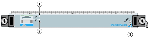
The 1-Port Channelized STM-1/OC-3 SPA has two types of LEDs: an A/L LED for each port and a STATUS LED, as shown in Figure 2-15.
Figure 2-15 1-Port Channelized STM-1/OC-3 SPA Faceplate
The 1-Port Channelized STM-1/OC-3 SPALEDs are described in Table 2-25.
1-Port Channelized STM-1/OC-3 SPA Interface Specifications
The framer processes incoming and outgoing SONET or SDH frames. The framer operates at OC-3c/STM-1 line rates (155.52 Mbps).
Packet data is transported with a user-configured encapsulation (such as Point-to-Point Protocol [PPP]) and is mapped into the STS-3c/STM-1 frame.
The 1-Port Channelized STM-1/OC-3 SPA interface is compliant with RFC 1619, PPP over SONET/SDH, and RFC 1662, PPP in HDLC-like Framing. The 1-Port Channelized STM-1/OC-3 SPA also provides support for SNMP v1 agent (RFC 1155-1157), and Management Information Base (MIB) II (RFC 1213).
1-Port Channelized STM-1/OC-3 SPA Cables and Connectors
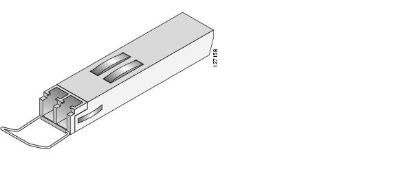
The 1-Port Channelized STM-1/OC-3 SPA uses a small form-factor pluggable (SFP) optical transceiver module installed in each port for SONET and SDH single-mode and multimode optical fiber connection (see Figure 2-16).
Figure 2-16 SFP Optics Module
The SFP optical transceiver modules used with the 1-Port Channelized STM-1/OC-3 SPA provide the following optical fiber options:
•
Use a multimode optical fiber that has a core/cladding diameter of 62.5/125 microns.
•
Use a single-mode optical fiber that has a modal-field diameter of 8.7 ±0.5 microns. (Nominal diameter is approximately 10/125 microns.)
For single-mode and multimode optical fiber connections, you can use either a duplex LC-type cable (see Figure 2-17) or two simplex LC-type cables, one for transmit (TX) and one for receive (RX).
Use single-mode (for intermediate- or long-reach configurations) or multimode optical fiber cable to connect your router to a network or to connect two 1-Port Channelized STM-1/OC-3 SPA-equipped routers back to back.
Long-range SFP optical transceiver modules (for long-reach configurations) cannot be connected back-to-back without using an attenuator between the two of them.
Figure 2-17 LC Type Cables
1-Port OC-48c/STM-16 POS SPA Overview
The 1-Port OC-48c/STM-16 POS SPA is a single-height SPA that is installed in a SIP subslot. The 1-Port OC-48c/STM-16 POS SPA provides RPR over SONET (IEEE 802.17), SRP over SONET (Cisco Proprietary), and Packet over SONET (POS) network connectivity with a bandwidth of 9.95 Gbps.
For more information about SPA bandwidth, see the "Bandwidth Oversubscription" topic in this chapter. For more information about SPAs and their compatibility with SIPs and modular optics, see the "SIP and SPA Product Overview" chapter in this guide.
The following sections describe the 1-Port OC-48c/STM-16 POS SPA:
•
•
•
1-Port OC-48c/STM-16 POS SPA LEDs
The 1-Port OC-48c/STM-16 POS SPA has six LEDs, as shown in Figure 2-18.
Figure 2-18 1-Port OC-48c/STM-16 POS SPA Faceplate
WRAP LED
CARRIER LED
PASSTHRU LED
ACTIVE LED
MATESYNC LED
A/L (Active Loopback) LED
C/A (Carrier/Alarm) LED
STATUS LED
Note
The 1-Port OC-48c/STM-16 POS SPA LEDs are described in Table 2-26.
1-Port OC-48c/STM-16 POS SPA Interface Specifications
The framer processes incoming and outgoing SONET or SDH frames. The framer operates at OC-48c/STM-64 line rates (9.95 Gbps).
Packet data is transported with a user-configured encapsulation (such as Point-to-Point Protocol [PPP]) and is mapped into the STS-48/STM-64 frame.
The 1-Port OC-48c/STM-16 POS SPA interface is compliant with the following RFCs:
•
•
RFC 2615, PPP over SONET/SDH The 1-Port OC-192c/STM-64 POS/RPR XFP SPA also provides support for SNMP v1 agent (RFC 1155-1157) and RFC 1213:
•
•
•
•
1-Port OC-48c/STM-16 POS SPA Optical Transceiver Modules, Connectors, and Cables
The 1-Port OC-48c/STM-16 POS SPA uses a single-mode, 9.95 Gbps, OC-48 optical fiber (SONET STS-48) optical transceiver module for SONET connection to the network.
The 1-Port OC-48c/STM-16 POS SPA supports the following type of optical transceiver module:
•
•
•
Use a single-mode optical fiber that has a modal-field diameter of 8.7 ±0.5 microns (nominal diameter is approximately 10/125 microns) to connect your router to a network.
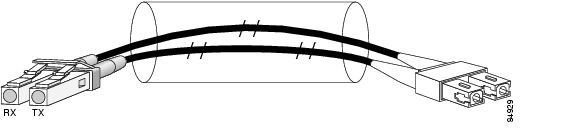
Figure 2-19 shows the cable type for use with the XFP optical transceiver module on the 1-Port OC-48c/STM-16 POS SPA.
Figure 2-19 LC-Type Cable for the SFP Optical Transceiver Modules
Note
Mate Interface Cables
The 1-Port OC-48c/STM-16 POS SPA supports two mate interface configurations:
•
•
Two 1-Port OC-48c/STM-16 POS SPAs are connected using a 40-pin connector copper mate cable. The length of the cables allow only two possible connection scenarios, next slot horizontal and same slot vertical. This assumes that the chassis is mounted vertically. Figure 2-20 shows the mate cables used to connect the SPAs.
Figure 2-20 SPA Mate Cables
Long length RPR mate cable for single port RPR SPAs (CBL-RPR-OC48-L)
Short length RPR mate cable for single port RPR SPAs (CAB-RPR-OC48-S)
Note
1-Port OC-192c/STM-64 POS SPA Overview
The 1-Port OC-192c/STM-64 POS/RPR SPA is a double-height SPA that is installed in two SIP subslots. The 1-Port OC-192c/STM-64 POS/RPR SPA provides SONET and SDH network connectivity with a bandwidth of 9.95 Gbps.
For more information about SPA bandwidth, see the "Bandwidth Oversubscription" section on page 2-2. For more information about SPAs and their compatibility with SIPs and modular optics, see the "SIP and SPA Compatibility" chapter in this guide.
The 1-Port OC-192c/STM-64 POS/RPR SPA uses a single,10-Gbps fixed optical receptacle allowing a connection to single-mode optical fiber. For more information on the optical fiber cables used with this SPA, see the "1-Port OC-192c/STM-64 POS/RPR SPA Fixed Optical Transceiver, 40-Pin Connector, and Cables" section.
The following sections describe the 1-Port OC-192c/STM-64 POS/RPR SPA:
•
•
•
1-Port OC-192c/STM-64 POS/RPR SPA LEDs
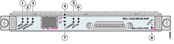
The 1-Port OC-192c/STM-64 POS/RPR SPA has six LEDs, as shown in Figure 2-21.
Figure 2-21 1-Port OC-192c/STM-64 POS/RPR SPA Faceplate
Note
The 1-Port OC-192c/STM-64 POS/RPR SPA LEDs are described in Table 2-27.
1-Port OC-192c/STM-64 POS/RPR SPA Interface Specifications
The 1-Port OC-192c/STM-64 POS/RPR SPA contains a SONET/SDH framer to process incoming and outgoing SONET or SDH frames. The framer operates at OC-192/STM-64 line rates (9.95 Gbps).
Packet data is transported with a user-configured encapsulation (such as Point-to-Point Protocol [PPP]) and is mapped into the STS-192c/STM-64 frame.
The 1-Port OC-192c/STM-64 POS/RPR SPA interface is compliant with the following RFCs:
•
•
•
The 1-Port OC-192c/STM-64 POS/RPR SPA also provides support for SNMP v1 agent (RFC 1155-1157) and RFC 1213:
•
•
•
•
1-Port OC-192c/STM-64 POS/RPR SPA Fixed Optical Transceiver, 40-Pin Connector, and Cables
The 1-Port OC-192c/STM-64 POS/RPR SPA uses fixed optical transceivers, one for receive (RX) and one for transmit (TX), for SONET and SDH connection to the network. In Cisco IOS Release 12.0(31)S, only long-reach (LR) optics are supported.
Cisco Systems qualifies the optics that are approved for use with its SPAs. As of Cisco IOS Release 12.0(31)S Cisco IOS XR Software Release 3.2, the XFP-10GLR-OC192SR and the XFP-10GER-OC192IR are the only optical transceiver modules qualified for use.
The 1-Port OC-192c/STM-64 POS/RPR SPA uses single-mode SC-type connectors:
•
Use a single-mode optical fiber that has a modal-field diameter of 8.7 ±0.5 microns. (Nominal diameter is approximately 10/125 microns.)
Use a single-mode optical fiber cable to connect your router to a network.
Note
Figure 2-22 shows the cable type for use with the fixed optical transceiver module on the 1-Port OC-192c/STM-64 POS/RPR SPA.
Figure 2-22 SC-Type Connectors for the Fixed Optical Transceivers
Mate Interface Cables
The 1-Port OC-192c/STM-64 POS/RPR SPA supports two mate interface configurations:
•
•
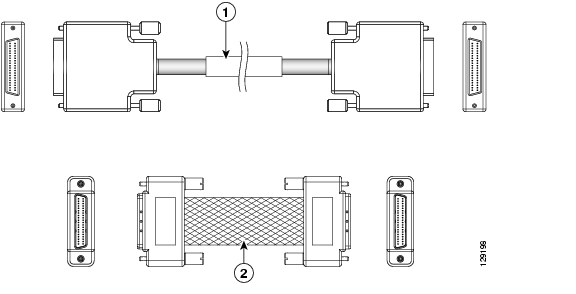
Two 1-Port OC-192c/STM-64 POS/RPR SPAs are connected using a 40-pin connector copper mate cable. The length of the cables allow only two possible connection scenarios, next slot horizontal and same slot vertical. This assumes that the chassis is mounted vertically. Figure 2-23 shows the mate cables used to connect the SPAs.
Figure 2-23 SPA Mate Cables
Long length RPR mate cable for single port RPR SPAs (CBL-RPR-OC192-L)
Short length RPR mate cable for single port RPR SPAs (CAB-RPR-OC192-S)
Note
1-Port OC-192c/STM-64 POS RPR XFP SPA Overview
The 1-Port OC-192c/STM-64 POS/RPR XFP SPA is a single-height SPA that is installed in one SIP subslot. The 1-Port OC-192c/STM-64 POS/RPR XFP SPA provides SONET and SDH network connectivity with a bandwidth of 9.95 Gbps.
For more information about SPA bandwidth, see the "Bandwidth Oversubscription" section in this chapter. For more information about SPAs and their compatibility with SIPs and modular optics, see the product overview chapter in this guide.
The 1-Port OC-192c/STM-64 POS/RPR XFP SPA uses a 10-Gbps small form-factor pluggable optical receptacle for each port allowing connection to single-mode optical fiber. For more information on the optical fiber cables used with this SPA, see the "1-Port OC-192c/STM-64 POS/RPR XFP SPA Optical Transceiver Modules, Connectors, and Cables" section.
The following sections describe the 1-Port OC-192c/STM-64 POS/RPR XFP SPA:
•
•
•
1-Port OC-192c/STM-64 POS/RPR XFP SPA LEDs
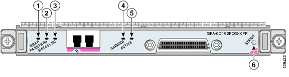
The 1-Port OC-192c/STM-64 POS/RPR XFP SPA has six LEDs, as shown in Figure 2-24.
Figure 2-24 1-Port OC-192c/STM-64 POS/RPR XFP SPA Faceplate
Note
Table 2-28 describes the 1-Port OC-192c/STM-64 POS/RPR XFP SPA LEDs.
1-Port OC-192c/STM-64 POS/RPR XFP SPA Interface Specifications
The framer processes incoming and outgoing SONET or SDH frames. The framer operates at OC-192c/STM-64 line rates (9.95 Gbps).
Packet data is transported with a user-configured encapsulation (such as Point-to-Point Protocol [PPP]) and is mapped into the STS-192c/STM-64 frame.
The 1-Port OC-192c/STM-64 POS/RPR XFP SPA interface is compliant with the following RFCs:
•
•
The 1-Port OC-192c/STM-64 POS/RPR XFP SPA also provides support for SNMP v1 agent (RFC 1155-1157) and RFC 1213:
•
•
•
•
1-Port OC-192c/STM-64 POS/RPR XFP SPA Optical Transceiver Modules, Connectors, and Cables
The 1-Port OC-192c/STM-64 POS/RPR XFP SPA uses a single-mode, 9.95 Gbps, OC-192c optical fiber (SONET STS-192c or SDH STM-64) optical transceiver module for SONET and SDH connection to the network.
The 1-Port OC-192c/STM-64 POS/RPR XFP SPA supports the following types of optical transceiver module:
•
•
•
Cisco Systems qualifies the optics that are approved for use with its SPAs. As of Cisco IOS Release 12.0(31)S, the above-listed XFPs are the only optical transceiver modules qualified for use.
Use a single-mode optical fiber that has a modal-field diameter of 8.7 ±0.5 microns (nominal diameter is approximately 10/125 microns) to connect your router to a network.
Figure 2-25 shows the cable type for use with the XFP optical transceiver module on the 1-Port OC-192c/STM-64 POS/RPR XFP SPA.
Figure 2-25 LC-Type Cable for the XFP Optical Transceiver Modules
Note
OC-192 Module Connections
Table 2-29 shows the OC-192 specifications for use with the 1-Port OC-192c/STM-64 POS/RPR XFP SPA.
Mate Interface Cables
The 1-Port OC-192c/STM-64 POS/RPR XFP SPA supports two mate interface configurations:
•
•
Two 1-Port OC-192c/STM-64 POS/RPR XFP SPAs are connected using a 40-pin connector copper mate cable. The length of the cables allow only two possible connection scenarios, next slot horizontal and same slot vertical. This assumes that the chassis is mounted vertically. Figure 2-26 shows the mate cables used to connect the SPAs.
Figure 2-26 SPA Mate Cables
Long length RPR mate cable for single port RPR SPAs (CBL-RPR-OC192-L)
Short length RPR mate cable for single port RPR SPAs (CAB-RPR-OC192-S)
Note
2-Port OC-48 POS RPR SPA Overview
The following sections describe the 2-Port OC48-POS/RPR SPA:
•
•
•
2-Port OC48-POS/RPR SPA LEDs
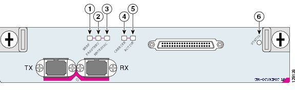
The 2-Port OC48-POS/RPR SPA has five LEDs, as shown in Figure 2-27.
Figure 2-27 2-Port OC48-POS/RPR SPA Faceplate
PTH (Pass-Through) LED
ACT (Active Loopback) LED
PRT (Protect) LED
STATUS LED
CAR (Carrier/Alarm) LED
The 2-Port OC48-POS/RPR SPA LEDs are described in Table 2-30.
2-Port OC48-POS/RPR SPA Interface Specifications
The physical layer interface for the 2-Port OC48-POS/RPR SPA is Optical Carrier-48 (OC-48), and the 2-Port OC48-POS/RPR SPA is designed to comply with POS specifications. The 2-Port OC48-POS/RPR SPA provides two 2.488-Gbps network interfaces for all supported platforms.
2-Port OC48-POS/RPR SPA Cables, Optical Transceiver Modules, and Connectors
Use single-mode (for intermediate-configurations) optical fiber cable to connect your router to a network or to connect two OC-48-equipped routers back-to-back.
The 2-Port OC48-POS/RPR SPA supports the following types of optical transceiver modules:
•
•
•
Each port on the 2-Port OC48-POS/RPR SPA has one duplex LC-type receptacle. For single-mode optical fiber connections, you can use either a duplex LC-type cable (see Figure 2-28) or two simplex LC-type cables, one for transmit (TX) and one for receive (RX).
Figure 2-28 Duplex Patch Cable with LC-Type Connectors
2-Port, 4-Port, and 8-Port OC-3c/STM-1 and OC-12c/STM-4 POS SPA, 4-Port OC-3c/STM-1 POS SPA, and 8-Port OC-3c/STM-1 POS SPA Overview
This section provides the hardware overview for the following SPAs:
•
•
•
•
•
The 2-Port, 4-Port, and 8-Port OC-3c/STM-1 and OC-12c/STM-4 POS SPA and the 4-Port and 8-Port OC-3c/STM-1 POS SPA are single-height SPAs that each install into one SIP subslot. The SPAs with small form-factor pluggable (SFP) optical transceiver modules provide Optical Carrier Level (OC-N) for SONET and Synchronous Transport Module (STM-N) for SDH network connectivity. For the OC-3 SPAs, the per-port bandwidth is 155.52 Mbps. For the OC-12 SPAs, any given channel can be configured as either OC-3 or OC-12, so the per-port bandwidth can be either 155.52 Mbps or 622.08 Mbps respectively, depending on the customer configuration.
Note
The 8-port OC-12c/STM-4 POS SPA is a full rate SPA; therefore, it can only be installed in subslots 1 or 2 of the SIP. The 4-Port and 8-Port OC-3c/STM-1 POS SPA and the 2-Port, 4-Port, and 8-Port OC-3c/STM-1 and OC-12c/STM-4 POS SPAs are all half rate SPAs.
For more information about SPA bandwidth, see the "Bandwidth Oversubscription" topic in this chapter. For more information about SPAs and their compatibility with SIPs and modular optics, see the "SIP and SPA Product Overview" chapter in this guide.
The following sections describe the 2-Port, 4-Port, and 8-Port OC-3c/STM-1 and OC-12c/STM-4 POS SPA and the 4-Port and 8-Port OC-3c/STM-1 POS SPA:
•
2-Port, 4-Port, and 8-Port OC-3c/STM-1 and OC-12c/STM-4 POS SPA and 4-Port and 8-Port OC-3c/STM-1 POS SPA LEDs
The 2-Port, 4-Port, and 8-Port OC-3c/STM-1 and OC-12c/STM-4 POS SPA and the 4-Port and 8-Port OC-3c/STM-1 POS SPA have three LEDs: two LEDs for each port on the SPA and one STATUS LED. Figure 2-29 shows the 8-Port OC-3c/STM-1 and OC-12c/STM-4 POS SPA faceplate.
Note
Figure 2-29 8-Port OC-3c/STM-1 and OC-12c/STM-4 POS SPA Faceplate
The 2-Port, 4-Port, and 8-Port OC-3c/STM-1 and OC-12c/STM-4 POS SPA and the 4-Port and 8-Port OC-3c/STM-1 POS SPA LEDs are described in Table 2-31.
2-Port, 4-Port, and 8-Port OC-3c/STM-1 and OC-12c/STM-4 POS SPA and 4-Port and 8-Port OC-3c/STM-1 POS SPA Interface Specifications
The framer processes incoming and outgoing SONET or SDH frames. The framer operates at OC-3 line rates (155.52 Mbps) and OC-12 line rates (622.08 Mbps). Packet data is transported with a user-configured encapsulation (such as Point-to-Point Protocol [PPP]) and is mapped into the layer 2 frame.
The 2-Port, 4-Port, and 8-Port OC-3c/STM-1 and OC-12c/STM-4 POS SPA and the 4-Port and 8-Port OC-3c/STM-1 POS SPA interface complies with the following IETF RFCs:
•
•
•
2-Port, 4-Port, and 8-Port OC-3c/STM-1 and OC-12c/STM-4 POS SPA and 4-Port and 8-Port OC-3c/STM-1 POS SPA Optical Transceiver Modules and Cables
The 2-Port, 4-Port, and 8-Port OC-3c/STM-1 and OC-12c/STM-4 POS SPA and the 4-Port and 8-Port OC-3c/STM-1 POS SPA use an SFP optical transceiver module installed in each port for SONET and SDH single-mode and multimode optical fiber connection (see Figure 2-30).
Cisco Systems qualifies the optics that are approved for use with its SPAs. The 2-Port, 4-Port, and 8-Port OC-3c/STM-1 and OC-12c/STM-4 POS SPA when configured as OC-3 and the 4-Port and 8-Port OC-3c/STM-1 POS SPA support the following types of optical transceiver modules:
•
•
•
•
•
The 2-Port, 4-Port, and 8-Port OC-3c/STM-1 and OC-12c/STM-4 POS SPA when configured as OC-12 supports the following types of optical transceiver modules:
•
•
•
•
•
Figure 2-30 SFP Optics Module
The SFP optical transceiver modules used with the 2-Port, 4-Port, and 8-Port OC-3c/STM-1 and OC-12c/STM-4 POS SPA configured for OC-3 and the 4-Port and 8-Port OC-3c/STM-1 POS SPA provide the following optical fiber options:
•
Use a multimode optical fiber that has a core/cladding diameter of 62.5/125 microns.
•
Use a single-mode optical fiber that has a modal-field diameter of 8.7 ± 0.5 microns. (Nominal diameter is approximately 10/125 microns.)
The SFP optical transceiver modules used with the 2-Port, 4-Port, and 8-Port OC-3c/STM-1 and OC-12c/STM-4 POS SPA configured for OC-12 provide the following optical fiber options:
•
Use a multimode optical fiber that has a core/cladding diameter of 62.5/125 microns.
•
Use a single-mode optical fiber that has a modal-field diameter of 8.7 ± 0.5 microns. (Nominal diameter is approximately 10/125 microns.)
For single-mode and multimode optical fiber connections, you can use either a duplex LC-type cable (see Figure 2-31) or two simplex LC-type cables, one for transmit (TX) and one for receive (RX).
Use single-mode (for short-, intermediate- or long-reach configurations) or multimode optical fiber cable to connect your router to a network or to connect two OC-3-equipped or OC-12-equipped routers back-to-back. Long-range SFP optical transceiver modules (for long-reach configurations) cannot be connected back-to-back without using an attenuator between the two of them.
Figure 2-31 LC-Type Cable
![]()
![]()
![]()
![]()
![]()
![]()
![]()
![]()
Posted: Wed Oct 31 04:16:40 PDT 2007
All contents are Copyright © 1992--2007 Cisco Systems, Inc. All rights reserved.
Important Notices and Privacy Statement.