|
|

Table Of Contents
Overview: Cisco 12000 Series Router SPA Interface Processors
SIP Software and Hardware Compatibility
Cisco 12000 SIP-400 Board Components
Cisco 12000 SIP-400 Physical Specifications
SPA Slot Numbering on the Cisco 12000 SIP-400
SPA Interface Addresses on the Cisco 12000 SIP-400
Cisco 12000 SIP-600 Board Components
Cisco 12000 SIP-600 Physical Specifications
SPA Subslot Numbering on the Cisco 12000 SIP-600
SPA Interface Addresses on the Cisco 12000 SIP-600
Cisco 12000 SIP-401 Board Components
Cisco 12000 SIP-401 Physical Specifications
SPA Slot Numbering on the Cisco 12000 SIP-401
SPA Interface Addresses on the Cisco 12000 SIP-401
Cisco 12000 SIP-501 Board Components
Cisco 12000 SIP-501 Physical Specifications
SPA Subslot Numbering on the Cisco 12000 SIP-501
SPA Interface Addresses on the Cisco 12000 SIP-501
Cisco 12000 SIP-601 Board Components
Cisco 12000 SIP-601 Physical Specifications
SPA Subslot Numbering on the Cisco 12000 SIP-601
SPA Interface Addresses on the Cisco 12000 SIP-601
Overview: Cisco 12000 Series Router SPA Interface Processors
Release 12.0(32)SY1, OL-8831-01, Rev. G6, July 19, 2007
This chapter describes the SPA interface processors (SIPs) that are supported on the Cisco 12000 series router and contains the following sections:
•
Router Hardware Installation
•
•
•
•
•
•
SIP and SPA Compatibility
Table 1-1 shows the SPAs that are supported on the Cisco 12000 series router and the SIPs that support them:
Router Hardware Installation
For Cisco 12000 series router hardware installation and configuration information, refer to the installation and configuration guide for your router. The guide includes information on the router switch fabric and how it affects the operation of SIPs, as well as SIP slot locations, slot width, and other requirements.
Note
Supported Platforms
SIPs are supported on all Cisco 12000 series routers. The 2.5G ISE SIP is supported on the Cisco 12016, 124xx, and 128xx routers. The Cisco 12000 SIP-401, the Cisco 12000 SIP-501, the Cisco 12000 SIP-600, and the Cisco 12000 SIP-601are supported on the Cisco 124xx and 128xx routers.
Note
Power Management
Different types of power supplies are used in Cisco 12000 series routers. The chassis power supply configuration may cause limitations on the number of SPAs that can be installed in the chassis. If the number of SPAs installed in the chassis draw more power than the power supply configuration supports, the console displays a warning indicating that the configured power supply budget has been exceeded.
Power management is described in the Cisco 12000 series router chassis installation guides. Please refer to the chassis installation guide for your router for information about power management.
SIP Summary
Summary descriptions of all SIPs supported on the Cisco 12000 series router are shown in Table 1-2.
Table 1-2 SIP Summary
Cisco 12000 SIP-400
12000-SIP-400
2.5G ISE SPA Interface Processor
4 single-width, single-height
Engine 3 (ISE)
Cisco 12000 SIP-600
12000-SIP-600
10G Engine 5 SPA Interface Processor
2 single-width, double-height
2 single-width, single-height1
1 dual-width, double-height2
Engine 5
Cisco 12000 SIP-401
12000-SIP-401
2.5G Engine 5 SPA Interface Processor
2 single-width, double-height
4 single-width, single-height
1 dual-width, double-height
Engine 5
Cisco 12000 SIP-501
12000-SIP-501
5G Engine 5 SPA Interface Processor
2 single-width, double-height
4 single-width, single-height
1 dual-width, double-height
Engine 5
Cisco 12000 SIP-601
12000-SIP-601
10G Engine 5 SPA Interface Processor
2 single-width, double-height
4 single-width, single-height
1 dual-width, double-height
Engine 5
1 Requires that a blank module filler plate be installed in the bottom subslot.
2 Requires the removal of the central septum between the SPA subslots.
SIP Software and Hardware Compatibility
For software configuration information, refer to the Cisco IOS software configuration and command reference publications for the installed Cisco IOS release. Also refer to the Cisco IOS software release notes for additional information. Table 1-3 lists the Cisco IOS releases that are compatible with supported SIPs.
To ensure compatibility with the software, your SIPs should have a specific hardware revision number. The number is printed on a label affixed to the component side of the card. The hardware revision number can be displayed by using the show diags slot-number command. Table 1-3 lists the hardware revision number for all supported SIPs.
The show version and show hardware commands display the current hardware configuration of the router, including the system software version that is currently loaded and running. For complete descriptions of show commands, refer to the Cisco IOS Configuration Fundamentals Configuration Guide and the Cisco IOS Configuration Fundamentals Command Reference for the installed Cisco IOS release.
Cisco 12000 SIP-400 Overview
The following sections describe the Cisco 12000 SIP-400:
•
•
•
•
Cisco 12000 SIP-400 Board Components
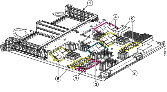
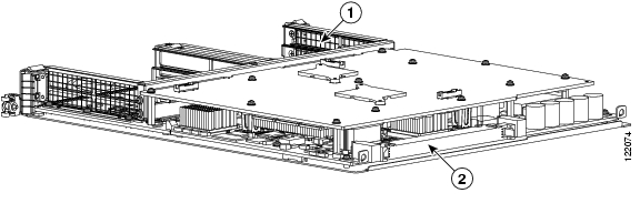
The main Cisco 12000 SIP-400 board components are shown in Figure 1-1. Board reference designators are indicated after the board component name.
Figure 1-1 Cisco 12000 SIP-400 Board—Rear View
SPA enclosure
Four packet memory SODIMM sockets (not field serviceable)
Backplane connector
Four TLU/PLU memory SODIMM sockets (not field serviceable)
Route memory SODIMM
Cisco 12000 SIP-400 LEDs
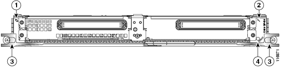
The Cisco 12000 SIP-400 has one LED, as shown in Figure 1-2.
Figure 1-2 Cisco 12000 SIP-400 Face Plate
The Cisco 12000 SIP-400 LEDs are described in Table 1-4.
Table 1-4 Cisco 12000 SIP-400 LED
Status
Yellow
On
IOS is loaded and SIP is ready to be enabled.
Green
On
SIP is active.
Cisco 12000 SIP-400 Physical Specifications
The Cisco 12000 SIP-400 physical specifications are shown in the following table.
SPA Slot Numbering on the Cisco 12000 SIP-400
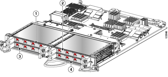
The Cisco 12000 SIP-400 accepts 4 single-width, single-height SPAs.
Figure 1-3 shows a Cisco 12000 SIP-400 with 4 SPAs installed. The top leftmost SPA slot is subslot 0; the top rightmost SPA slot is subslot 1; the bottom leftmost SPA slot is subslot 2; the bottom rightmost SPA slot is subslot 3.
Figure 1-3 Cisco 12000 SIP-400 with SPAs Installed
SPA Interface Addresses on the Cisco 12000 SIP-400
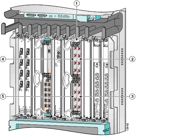
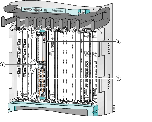
A Cisco 12000 Series Router identifies a SPA interface address by its SIP slot number, SPA subslot, and port number on the SPA, in the format slot/subslot/port. Subslots and ports are numbered starting from 0, so each Cisco 12000 SIP-400 has four subslots. A 4-port SPA would have ports 0 to 3. For example, the interface address of the second port on a 4-port SPA located in the first SIP subslot, where the SIP is inserted into router line card slot 6 is 6/0/1.
Figure 1-4 Cisco 12000 Series Router with Cisco 12000 SIP-400 Installed
Router slot number 6
SPA subslot 2 with ports 6/2/0 to 6/2/3
SPA subslot 0 with ports 6/0/0 to 6/0/3
SPA subslot 3 with ports 6/3/0 to 6/3/3
SPA subslot 1 with ports 6/1/0 to 6/1/3
Cisco 12000 SIP-600 Overview
The following sections describe the Cisco 12000 SIP-600:
•
•
•
•
Cisco 12000 SIP-600 Board Components
The main Cisco 12000 SIP-600 board components are shown in Figure 1-5.
Figure 1-5 Cisco 12000 SIP-600 Board—Rear View
Cisco 12000 SIP-600 LEDs
The Cisco 12000 SIP-600 supports 2 single-width, double-height SPAs, 2 single-width, single-height SPAs, or 1 dual-width, double-height SPA. The Cisco 12000 SIP-600 face plate has one Status LED. Figure 1-6 shows the Cisco 12000 SIP-600 face plate with 2 single-width, single-height SPAs.
Figure 1-6 Cisco 12000 SIP-600 Face Plate
The Cisco 12000 SIP-600 LEDs are described in Table 1-6.
Table 1-6 Cisco 12000 SIP-600 LEDs
Status
Yellow
On
SIP is powered and IOS is loading.
Green
On
SIP is active.
Cisco 12000 SIP-600 Physical Specifications
The Cisco 12000 SIP-600 physical specifications are shown in the following table.
SPA Subslot Numbering on the Cisco 12000 SIP-600
The Cisco 12000 SIP-600 accepts 2 single-width SPAs or 1 dual-width SPA.
Figure 1-7 shows a Cisco 12000 SIP-600 with 2 SPAs installed. The left SPA slot is subslot 0 and the right SPA slot is subslot 1. If one dual-width SPA is installed, it is recognized as being in subslot 0.
Figure 1-7 Subslot Locations for the 1-Port 10-Gigabit Ethernet SPA
Table 1-8 Subslot Locations for the 1-Port 10-Gigabit Ethernet SPA
1
Subslot 0
2
Subslot 1
SPA Interface Addresses on the Cisco 12000 SIP-600
A Cisco 12000 Series Router identifies a SPA interface address by its SIP slot number, SPA subslot, and port number on the SPA, in the format slot/subslot/port. Subslots and ports are numbered starting from 0, so each Cisco 12000 SIP-600 has two subslots 0 (left) and 1 (right). For example, the interface address of a 1-port SPA located in the second SIP subslot, where the SIP is inserted into router line card slot 3 is 3/1/0. Figure 1-8 shows the slot, subslot, and port locations for the 1-Port 10-Gigabit Ethernet SPA and the 10-Port Gigabit Ethernet SPA.
Figure 1-8 Slot, Subslot, and Port Locations for the 1-Port 10-Gigabit Ethernet SPA and the 10-Port Gigabit Ethernet SPA.
Table 1-9 Slot and Port Locations for the 1-Port 10-Gigabit Ethernet SPA
1
Slot 3
2
Subslot 0, Port 3/0/0
3
Subslot 1, Ports 3/1/0 to 3/1/9
Cisco 12000 SIP-401 Overview
The following sections describe the Cisco 12000 SIP-401:
•
•
•
•
Cisco 12000 SIP-401 Board Components
The main Cisco 12000 SIP-501 board components are shown in Figure 1-9.
Figure 1-9 Cisco 12000 SIP-401 Board—Rear View
Cisco 12000 SIP-401 LEDs
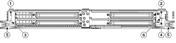
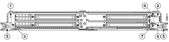
The Cisco 12000 SIP-401 has two LEDs, as shown in Figure 1-10.
Figure 1-10 Cisco 12000 SIP-401 Face Plate
SPA subslot 0
Ejector Levers
SPA subslot 1
Status LED
SPA subslot 2
Rate LED
SPA subslot 3
The Cisco 12000 SIP-401 LEDs are described in Table 1-10.
Cisco 12000 SIP-401 Physical Specifications
The Cisco 12000 SIP-401 physical specifications are shown in the following table.
SPA Slot Numbering on the Cisco 12000 SIP-401
The Cisco 12000 SIP-401 accepts 4 single-width, single-height SPAs.
Figure 1-11 shows a Cisco 12000 SIP-401 with 4 SPAs installed. The top leftmost SPA slot is subslot 0; the top rightmost SPA slot is subslot 1; the bottom leftmost SPA slot is subslot 2; the bottom rightmost SPA slot is subslot 3.
Figure 1-11 Cisco 12000 SIP-401 with SPAs Installed
SPA Interface Addresses on the Cisco 12000 SIP-401
A Cisco 12000 Series Router identifies a SPA interface address by its SIP slot number, SPA subslot, and port number on the SPA, in the format slot/subslot/port. Subslots and ports are numbered starting from 0, so each Cisco 12000 SIP-401 has four subslots. A 4-port SPA would have ports 0 to 3. For example, the interface address of the second port on a 4-port SPA located in the first SIP subslot, where the SIP is inserted into router line card slot 6 is 6/0/1.
Figure 1-12 Cisco 12000 Series Router with Cisco 12000 SIP-401 Installed
Router slot number 6
SPA subslot 2 with ports 6/2/0 to 6/2/3
SPA subslot 0 with ports 6/0/0 to 6/0/3
SPA subslot 3 with ports 6/3/0 to 6/3/3
SPA subslot 1 with ports 6/1/0 to 6/1/3
Cisco 12000 SIP-501 Overview
The following sections describe the Cisco 12000 SIP-501:
•
•
•
•
Cisco 12000 SIP-501 Board Components
The main Cisco 12000 SIP-501 board components are shown in Figure 1-13.
Figure 1-13 Cisco 12000 SIP-501 Board—Rear View
Cisco 12000 SIP-501 LEDs
The Cisco 12000 SIP-501 supports 4 single-height SPAs (the aggregate throughput should not exceed 2 full-rate SPAs); 2 double-height SPAs; 1 dual-width, double-height SPA, or a combination of single-height and double-height SPAs.
The interconnect between a SIP and a SPA can operate at either 2.5Gbps or 10Gbps. If the maximum capacity of a SPA is greater than 2.5Gbps the interconnect operates at 10Gbps and the SPA is a "full-rate" SPA. If the maximum capacity of a SPA is 2.5Gbps or less the interconnect operates at 2.5Gbps and the SPA is a "quarter-rate" SPA. The Cisco 12000 SIP-501 can support up to two full-rate SPAs, or one full-rate and three quarter-rate SPAs or four quarter-rate SPAs.
The Cisco 12000 SIP-501 face plate has one Status LED. Figure 1-14 shows the Cisco 12000 SIP-501 face plate with 4 single-width, single-height SPAs.
Figure 1-14 Cisco 12000 SIP-501 Face Plate
SPA subslot 0
Ejector Levers
SPA subslot 1
Status LED
SPA subslot 2
Rate LED
SPA subslot 3
The Cisco 12000 SIP-501 LEDs are described in Table 1-12.
Cisco 12000 SIP-501 Physical Specifications
The Cisco 12000 SIP-501 physical specifications are shown in the following table.
SPA Subslot Numbering on the Cisco 12000 SIP-501
The Cisco 12000 SIP-501 accepts up to 4 single-width SPAs or 1 dual-width SPA.
Figure 1-15 shows a Cisco 12000 SIP-501 with 2 SPAs installed. The left SPA slot is subslot 0 and the right SPA slot is subslot 1. If one dual-width SPA is installed, it is recognized as being in subslot 0.
Figure 1-15 Subslot Locations for the 1-Port 10-Gigabit Ethernet SPA
Table 1-14 Subslot Locations for the 1-Port 10-Gigabit Ethernet SPA
1
Subslot 0
2
Subslot 1
SPA Interface Addresses on the Cisco 12000 SIP-501
A Cisco 12000 Series Router identifies a SPA interface address by its SIP slot number, SPA subslot, and port number on the SPA, in the format slot/subslot/port. Subslots and ports are numbered starting from 0, so each Cisco 12000 SIP-601 has two subslots 0 (left) and 1 (right). For example, the interface address of a 1-port SPA located in the second SIP subslot, where the SIP is inserted into router line card slot 3 is 3/1/0. Figure 1-16 shows the slot, subslot, and port locations for the 1-Port 10-Gigabit Ethernet SPA and the 10-Port Gigabit Ethernet SPA.
Figure 1-16 Slot, Subslot, and Port Locations for the 1-Port 10-Gigabit Ethernet SPA and the 10-Port Gigabit Ethernet SPA.
Table 1-15 Slot and Port Locations for the 1-Port 10-Gigabit Ethernet SPA
1
Slot 3
2
Subslot 0, Port 3/0/0
3
Subslot 1, Ports 3/1/0 to 3/1/9
Cisco 12000 SIP-601 Overview
The following sections describe the Cisco 12000 SIP-601:
•
•
•
•
Cisco 12000 SIP-601 Board Components
The main Cisco 12000 SIP-601 board components are shown in Figure 1-17.
Figure 1-17 Cisco 12000 SIP-601 Board—Rear View
Cisco 12000 SIP-601 LEDs
The Cisco 12000 SIP-601 supports 4 single-height SPAs (the aggregate throughput should not exceed 2 full-rate SPAs); 2 double-height SPAs; 1 dual-width, double-height SPA, or a combination of single-height and double-height SPAs.
The interconnect between a SIP and a SPA can operate at either 2.5Gbps or 10Gbps. If the maximum capacity of a SPA is greater than 2.5Gbps the interconnect operates at 10Gbps and the SPA is a "full-rate" SPA. If the maximum capacity of a SPA is 2.5Gbps or less the interconnect operates at 2.5Gbps and the SPA is a "quarter-rate" SPA. The Cisco 12000 SIP-601 can support up to two full-rate SPAs, or one full-rate and three quarter-rate SPAs or four quarter-rate SPAs.
The Cisco 12000 SIP-601 face plate has one Status LED. Figure 1-18 shows the Cisco 12000 SIP-601 face plate with 2 single-width, single-height SPAs.
Figure 1-18 Cisco 12000 SIP-601 Face Plate
SPA subslot 0
Ejector Levers
SPA subslot 1
Status LED
SPA subslot 2
Rate LED
SPA subslot 3
The Cisco 12000 SIP-601 LEDs are described in Table 1-16.
Cisco 12000 SIP-601 Physical Specifications
The Cisco 12000 SIP-601 physical specifications are shown in the following table.
SPA Subslot Numbering on the Cisco 12000 SIP-601
The Cisco 12000 SIP-601 accepts 4 single-height SPAs (the aggregate throughput should not exceed 2 full-rate SPAs); 2 double-height SPAs; 1 dual-width, double-height SPA, or a combination of single-height and double-height SPAs.
Figure 1-19 shows a Cisco 12000 SIP-601 with 2 SPAs installed. The left SPA slot is subslot 0 and the right SPA slot is subslot 1. If one dual-width SPA is installed, it is recognized as being in subslot 0.
Figure 1-19 Subslot Locations for the 1-Port 10-Gigabit Ethernet SPA
Table 1-18 Subslot Locations for the 1-Port 10-Gigabit Ethernet SPA
1
Subslot 0
2
Subslot 1
SPA Interface Addresses on the Cisco 12000 SIP-601
A Cisco 12000 Series Router identifies a SPA interface address by its SIP slot number, SPA subslot, and port number on the SPA, in the format slot/subslot/port. Subslots and ports are numbered starting from 0, so each Cisco 12000 SIP-601 has two subslots 0 (left) and 1 (right). For example, the interface address of a 1-port SPA located in the second SIP subslot, where the SIP is inserted into router line card slot 3 is 3/1/0. Figure 1-20 shows the slot, subslot, and port locations for the 1-Port 10-Gigabit Ethernet SPA and the 10-Port Gigabit Ethernet SPA.
Figure 1-20 Slot, Subslot, and Port Locations for the 1-Port 10-Gigabit Ethernet SPA and the 10-Port Gigabit Ethernet SPA.
Table 1-19 Slot and Port Locations for the 1-Port 10-Gigabit Ethernet SPA
1
Slot 3
2
Subslot 0, Port 3/0/0
3
Subslot 1, Ports 3/1/0 to 3/1/9
![]()
![]()
![]()
![]()
![]()
![]()
![]()
![]()
Posted: Wed Jul 18 19:39:08 PDT 2007
All contents are Copyright © 1992--2007 Cisco Systems, Inc. All rights reserved.
Important Notices and Privacy Statement.