|
|

This chapter provides complete installation and cabling instructions for the Workgroup Concentrator. Specific topics covered in this chapter include the following:
Before you install the concentrator, read the chapter "Preparing for Installation."
There are many ways to configure and connect the concentrator. The following overview is specific to a UTP installation.
Before you install the concentrator, examine all shipping containers and contents for damage and check for missing items. If damage occurred to the containers during shipping, please notify your carrier. Unpack and examine the contents of the containers. You should have the following items:
Fill out the warranty registration sheet and mail or fax it to Cisco Systems, Inc. today. Report any missing parts and any damage not related to shipping to your customer service representative.
You can mount the concentrator on a wall, in a standard 19-inch rack, or place it on a desktop.
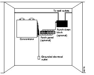
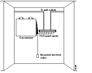
Figure 3-1 and Figure 3-2 show typical wall-mount installations. The optional wall-mount kit consists of the following items:
Following is the procedure for wall-mounting the concentrator:
Step 1 Remove the rubber feet from the concentrator, if necessary.
Step 2 Mark the location of the four support screws that will secure the concentrator to the wall. Use the template provided in the wall-mount kit. Make sure the screws will attach to a wall stud or some other support strong enough to hold the weight of the concentrator.
Step 3 Drill a pilot hole with a 1/16-inch (0.159 cm) bit at each mark you made for the location of a support screw.
Step 4 Screw the four 1/2-inch (1.27 cm) wood screws into the pilot holes, but not all the way. Allow them to protrude about 1/8-inch (0.317 cm).
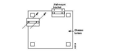
Step 5 Attach the wall-mount brackets to the concentrator with the supplied machine screws. Figure 3-3 shows where to install the brackets.
Step 6 If the plastic side panels are installed, remove them from the concentrator. To remove a side panel, hold it firmly with both hands and rock it slowly while you pull it away from the concentrator.
Step 7 Pick up the concentrator with both hands. The brackets should face away from you.
Step 8 Align the support screws with the holes in the brackets and push the concentrator against the wall, allowing the screws to go through the holes in the brackets.
Step 9 Hang the concentrator from the support screws.
Step 10 Tighten the support screws to secure the concentrator to the wall. Do not overtighten them.
Step 11 Replace the side panels on the concentrator.
Proceed to the section "What to Do after Installing the Hardware" later in this chapter.
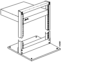
The concentrator can also be mounted in an open or closed EIA-standard
19-inch rack using the rack-mount bracket kit. The rack-mount bracket kit consists of the following materials:
Following is the procedure for rack-mounting the concentrator:
Step 1 Remove the plastic front panel and two side panels from the concentrator. Use both hands and gently rock each panel back and forth while pulling it away from the concentrator.
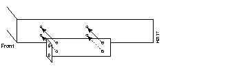
Step 2 Attach a rack-mount bracket to each side of the concentrator with the supplied Phillips machine screws. Mount each bracket with the tab positioned toward the front of the concentrator. (See Figure 3-4.)
Step 3 Secure both brackets tightly.
Step 4 Position the concentrator in the rack at the desired location and align the holes on the bracket tabs with the holes in the rack.
Step 5 Attach the concentrator to the rack using screws you provide.
(See Figure 3-5.)
Step 6 Replace the front panel and store the side panels.
Step 7 Proceed to the section "What to Do after Installing the Hardware."
The concentrator operates at a low noise level, which makes it suitable for any desktop environment. Place it in a clear and level location. Leave at least three inches (7.6 cm) clearance at the front for proper ventilation, and sufficient room at the rear for easy cable access. Proceed to the section "What to Do after Installing the Hardware."
 | Caution To prevent overheating damage, do not stack any other equipment on top of the concentrator chassis. |
After the chassis hardware is installed, proceed to the chapter "Connecting to the Network" for the procedures required to attach all cables to the concentrator. For the information necessary to configure the software portion of the system based on your requirements, proceed to the chapter "Configuring the System Software" and the appendix "Command Reference."
|
|