|
|

The A/B port cards are options that provide two additional CDDI or FDDI A or B ports. The line cards are options that provide up to 16 CDDI or FDDI ports per chassis.
The following procedures describe how to install and remove A/B port cards.
Install the A/B port card as follows:
Step 1 Unplug the power cable but, to channel ESD voltages to ground, ground the chassis and attach an ESD-preventive wrist strap.
 | Caution To prevent damage, never install or remove a port card with power applied to the concentrator. |
Step 2 Remove the two screws holding the blank plate to the concentrator, and remove the plate.
 | Caution To prevent damage to the FDDI transceivers on the FDDI port card (in step 3), gently press down on the port card as you insert it, so that the transceivers clear the chassis. The fit is snug. |
Step 3 Slide the port card into the slot in the concentrator. Make sure the metal base plate on the card slides under the guides in the concentrator. (See Figure C-1.)
Step 4 Secure the port card to the concentrator using the two Phillips head screws supplied with the port card.
 | Warning Invisible laser radiation may be emitted from the aperture ports of the single-mode FDDI card when no cable is connected. Avoid exposure and do not stare into open apertures. |

Step 5 Reinsert the power cable.
Remove an existing A/B port card as follows:
Step 1 Unplug the power cable but, to channel ESD voltages to ground, ground the chassis and attach an ESD-preventive wrist strap.
 | Caution To prevent damage, never install or remove a port card with power applied to the concentrator. |
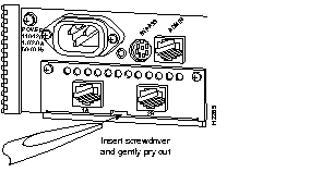
Step 2 Remove the two screws that secure the port card to the concentrator. (See Figure C-2.)
 | Warning Invisible laser radiation may be emitted from the aperture ports of the single-mode FDDI card when no cable is connected. Avoid exposure and do not stare into open apertures. |

 | Caution To prevent damage to the FDDI transceivers on the FDDI port card (in step 3), gently press down on the port card as you remove it so that the transceivers clear the chassis. The fit is snug. |
Step 3 Gently pry the A/B port card out of the slot with a flat-blade screwdriver. (See Figure C-2.)
Step 4 Reinsert the power cable.
Install the line cards as follows:
Step 1 Unplug the power cable but, to channel ESD voltages to ground, ground the chassis and attach an ESD-preventive wrist strap.
 | Caution To prevent damage, never install or remove a line card with power applied to the concentrator. |
Step 2 Remove the three screws holding the blank plate to the concentrator.
Step 3 Slide the line card into the slot in the concentrator. (See Figure C-3.) Make sure the edges of the line card are aligned in the plastic card guides in the concentrator.

Step 4 Push the card into the slot until the face plate is flush and the edge connectors at the rear of the card connect.
Step 5 Secure the card to the concentrator using the three Phillips head screws supplied with the port card.
Step 6 Reinsert the power cable.
Remove an existing line card as follows:
Step 1 Unplug the power cable but, to channel ESD voltages to ground, ground the chassis and attach an ESD-preventive wrist strap.
 | Caution To prevent damage, never install or remove a line card with power applied to the concentrator. |
Step 2 Remove the three screws holding the line card to the concentrator.
Step 3 Gently pry the line card out of the slot with a flat-blade screwdriver (see Figure C-3). After traveling approximately half an inch, the card will be free from the connector and will slide out easily.
Step 4 Place a new line card or blank plate over the opening in the concentrator.
Step 5 Reinsert the power cable.
|
|