|
|

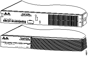
The CDDI/FDDI Workgroup Concentrator (Model Number WS-X1100) is a member of a family of concentrators that provide Copper Distributed Data Interface/multilevel transmission (CDDI/MLT-3) and single and multimode Fiber Distributed Data Interface (FDDI) connectivity. This concentrator combines the best features of compact, workgroup-style concentrators with the flexibility of chassis-style concentrators.
CDDI and FDDI ports can be mixed and added as needed, up to a maximum of 16 ports.
The concentrator can be further expanded by adding an optional A/B port card. This card adds two CDDI or FDDI ports that comply fully with the FDDI American National Standards Institute (ANSI) draft specification for A and B ports. In addition, optional CDDI and FDDI line cards are available, providing from four to eight additional ports per card.
Following are the available concentrator models:
You can place concentrators on a desktop, mount them on a wall, or mount them in an Electronic Industries Association (EIA)-compliant, 19-inch open or closed rack.
Following are the features of the Workgroup Concentrator:
Workgroup Concentrators fully comply with the FDDI Station Management (SMT) Specification, Revision 7.3 and include an SNMP agent for network management. A network administrator can monitor and control Workgroup Concentrators from anywhere on the network using any SNMP management application (for example, Workgroup Director network management software).
The front panel of the concentrator has light-emitting diode (LED) indicators for concentrator, ring, and port status, and port traffic. There is also a reset button that is used to reset the system. (See Figure 1-1.)
The LEDs on the concentrator front panel (see Figure 1-2) indicate the status of the concentrator (faulty/not faulty), the status of the ring, the configuration state of the dual ring, and the status of each port.
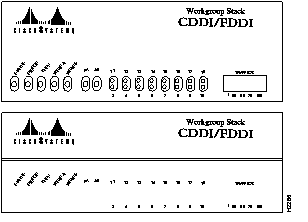
Following are descriptions of the status, ringop, thru, wrap A, wrap B, link status, and traffic meter LEDs.
The concentrator performs a series of self-tests and diagnostics. If all the tests pass, the status LED will be green. If any concentrator test fails, the status LED will be red.
The ringop LED indicates which ring is operational. (See Table 1-1.)
| Color | Meaning |
|---|---|
| Green | Primary ring is operational (secondary ring may also be operational). |
| Orange | Secondary ring is operational, primary ring is nonoperational. |
| Off | Both rings are nonoperational. |
In thru mode, indicated by the green thru LED, ports 1/A and 2/B are connected to the primary and secondary paths.
In wrap A mode, indicated by the green wrap A LED, port 2/B is isolated and port 1/A is connected to the ring.
In wrap B mode, indicated by the green wrap B LED, port 1/A is isolated and port 2/B is connected to the ring.
The link status LEDs (labeled 1/A, 2/B, and 3 through 18) indicate the connection state of each link. Table 1-2 explains what the colors of the LEDs indicate.
| Color | Meaning |
|---|---|
| Green | The link has connected properly with the remote device. |
| Orange | Signal detected, but the link has failed to connect or is in the process of connecting. A dual homed station causes the link status LED of an M1 port connected to the station A port to be orange. |
| Off | No signal detected. |
The traffic meter LED provides a visual indication (as an approximate percentage) of the current traffic load on the primary ring. (See Figure 1-3.)
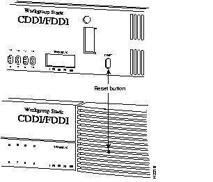
You can access the reset button, which is located behind the front panel, through a small hole approximately one and a half inches to the right of the traffic meter LED. Using a thin tool, such as a paper clip, press the button, then release it to reset the concentrator. (See Figure 1-4.)
The rear panel has three slots: one for A/B port cards, and two for line cards. The A/B port card slot is for an optional CDDI or FDDI A/B port card. The line card slots each accommodate a line card with from four to eight M ports for connecting to CDDI or FDDI A, B, or slave (S) ports. There is an AC power receptacle, an optical bypass switch connector and LED, and an EIA/TIA-232 port for the admin. interface. (See Figure 1-5.)
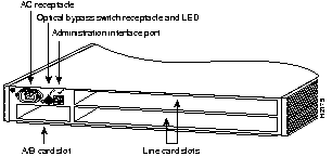
The AC power receptacle uses the AC power cord supplied with the concentrator. The power supply automatically accepts either 110 VAC or 230 VAC. To apply power, attach the power cord. To disconnect power, remove the power cord.
The six-pin mini-DIN connector is used to connect an external optical bypass switch to the concentrator. An activated bypass switch inserts the concentrator into the ring. Use a bypass switch only with the A/B port card option. If you install or remove an optical bypass switch, you must reset the concentrator. The optical bypass switch LED indicates the status of the device connected to the concentrator. When the LED is on, the bypass switch is activated and is in thru mode (the concentrator is attached to the dual ring).
To use the administration interface port (admin. interface), you can connect an EIA/TIA-232 terminal, modem, or workstation to the admin. port. You can also access the admin. interface from a remote host using Telnet. An RJ-45 cable and RJ-45-to-DB-25 data terminal equipment (DTE) adapter are provided for the admin. port. Refer to the appendix "Cabling Specifications" for the admin. port pinout.
The A/B card slot supports a single MAC dual attachment station (DAS) with dual homing configuration for FDDI. (A/B ports can also be configured as single attachment stations [SASs].) The slot also accepts CDDI/MLT-3 cards for unshielded twisted-pair (UTP) and shielded twisted-pair (STP) connections.
Figure 1-6 shows the following three models of A/B port cards:
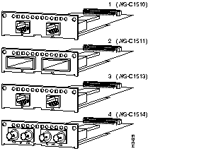
The A/B port cards allow the concentrator to connect to a dual ring as a peer connection or to the M port of another concentrator (cascaded tree configuration). To add an A and B port to the concentrator, insert an optional A/B port card. For A/B port card installation, see the appendix "Installing and Removing Port and Line Cards."
The line card slots (see Figure 1-5) support the following optional CDDI and FDDI line cards, which are shown in Figure 1-7. The appendix "Installing and Removing Port and Line Cards" contains procedures for installing and removing the line cards.
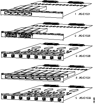
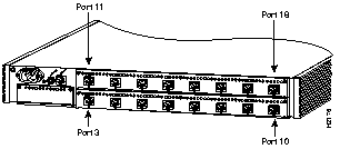
Figure 1-8 shows a concentrator with the maximum number of CDDI line card ports installed.
The CDDI-FDDI translator allows you to connect a device with an FDDI interface to a CDDI twisted-pair network. The translator has an FDDI MIC M port to connect to the FDDI station and a CDDI port to connect to the concentrator or wall plate with a modular cable.
The CDDI-FDDI translator includes an AC power adapter. Figure 1-9 shows the translator (Model Number WS-X703).
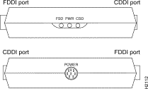
On the side of the translator you will find three status LEDs: FSD (FDDI signal detect), PWR (power), and CSD (CDDI signal detect).
Table 1-3 lists specifications for the CDDI/FDDI Workgroup Concentrator.
| Specification | Description |
|---|---|
| Physical (H x W x D) | 2.7 x 18 x 16'' (6.86 x 45.72 x 40.64 cm) |
| Weight | 16 lb (7.3 kg) |
| Power requirements | 2.5A @ 110 VAC, 60 Hz 1.6A @ 220 VAC, 50 Hz |
| Thermal dissipation | FDDI: 75W (maximum) CDDI: 65W (maximum) |
| Operating temperature | 32 to 104°F (0 to 40°C) |
| Storage temperature | -40 to 167°F (-40 to 75°C) |
| Relative humidity | 10% to 90% noncondensing |
| Electromagnetic emissions certifications | CDDI/FDDI: FCC Class A (47 CFR, Part 15) CDDI/FDDI: CISPR 22 Class A FDDI: VDE Class B |
| Safety | UL: 1950 CSA-C22.2 No. 950-M89 IEC 950 |
| Mounting | Desktop 19-inch rack (hardware included) Wall-mount (hardware included with optional kit) |
| Connectors | Multimode FDDI: MIC Single-mode FDDI: ST CDDI: RJ-45 Admin. port: RJ-45 |
| Ports | Four-port multimode FDDI line card Four-port single-mode FDDI line card Eight-port CDDI line card Eight-port multimode FDDI line card FDDI single-mode A/B port card FDDI multimode A/B port card Admin. interface port (EIA/TIA-232) |
| Fiber interface | 62.5/125-micron multimode fiber 50/125-micron multimode fiber 8/125-micron single-mode fiber |
| Network management | SMT 7.3 SNMP agent (RFC 1157) FDDI MIB (RFC 1285) MIB II (RFC 1213) Workgroup-specific MIB |
| LED indicators | Concentrator status Ringop Thru Wrap A Wrap B Traffic meter Link status (each link) Optical bypass switch (rear panel) |
| Maximum station-to-station cabling distance | 62.5/125 micron multimode fiber: 1.24 miles (2 km) 50/125 micron multimode fiber: 1.24 miles (2 km) 8/125-micron single-mode fiber: 1.24 miles (2 km) Single-mode fiber: 18.6 miles (30 km) Category 5 UTP: 328' (100 m) IBM Type 1 or Type 2 STP: 328' (100 m) |
| FDDI transmit power levels: Single-mode fiber Multimode fiber | Average optical power: Maximum: -4.0 dBm Minimum: -7.0 dBm Maximum: -14.0 dBm Minimum: -18.5 dBm |
| FDDI receive power levels: Single-mode fiber Multimode fiber | Average optical sensitivity: -33.0 dBm Average maximum input power: -14.0 dBm Average optical sensitivity: -34.0 dBm Average maximum input power: -14.0 dBm |
|
|