|
|

This appendix contains pinout information for CDDI concentrator and adapter ports, the admin. interface port, and the optical bypass switch connector.
Following are the cable considerations for the CDDI ports.
Figure D-1 shows the pinout for the CDDI/MLT-3 concentrator and adapter ports for A, B, M, and S ports.

Following are pinouts and cabling requirements for CDDI UTP wiring.
Table D-1 lists the pinout used for the CDDI/MLT-3 transmit and receive pairs.
| Pin | Signal | Pin | Signal |
| 1 | TX+ | 5 | - |
| 2 | TX- | 6 | - |
| 3 | - | 7 | RX+ |
| 4 | - | 8 | RX- |
The EIA 568-B wiring scheme is recommended. Table D-2 lists the EIA 568-B RJ-45 wiring scheme.
| Pin | Pair | Color | Pin | Pair | Color |
|---|---|---|---|---|---|
| 1 | 2 | White/orange | 5 | 1 | White/blue |
| 2 | 2 | Orange | 6 | 3 | Green |
| 3 | 3 | White/green | 7 | 4 | White/brown |
| 4 | 1 | Blue | 8 | 4 | Brown |
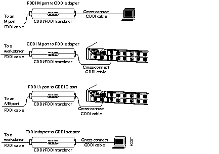
Figure D-2 shows examples of modular cross-connect cables used for CDDI/MLT-3 connections between various devices using the CDDI-FDDI translator.

The cabling for the concentrator admin. port must be straight-through, twisted-pair. Each of the four pairs of wires that make up the twisted-pair cable must be individually twisted.
Table D-3 and Table D-4 list the pinouts for the EIA/TIA-232 admin. port.
| Switch | Terminal (DTE) | |||
|---|---|---|---|---|
| Signal | RJ-45 Pin | Direction | DB-25 Pin | Signal |
| CTS | 1 | Output | 4 | RTS |
| DSR | 2 | Output | 20 | DTR |
| RXD | 3 | Output | 2 | TXD |
| GND | 4 | - | 7 | GND |
| GND | 5 | - | - | - |
| TXD | 6 | Input | 3 | RXD |
| DTR | 7 | Input | 6 | DSR |
| RTS | 8 | Input | 5 | CTS |
Table D-4 lists the pinout for a null-modem cable used with the admin. port. Modems are considered to be data communication equipment (DCE).
| Switch | Modem (DCE) | |||
|---|---|---|---|---|
| Signal | RJ-45 Pin | Direction | DB-25 Pin | Signal |
| CTS | 1 | Output | 5 | CTS |
| DSR | 2 | Output | 6 | DCD |
| RXD | 3 | Output | 3 | RXD |
| GND | 4 | - | 7 | GND |
| GND | 5 | - | - | GND |
| TXD | 6 | Input | 2 | TXD |
| DTR | 7 | Input | 20 | DTR |
| RTS | 8 | Input | 4 | RTS |
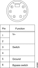
Figure D-3 shows the pinout and connector for the optical bypass switch. The connector is a standard female DIN type.

|
|