|
|

Table Of Contents
Before You Call for Technical Assistance
Solving Startup Problems by Using a Subsystems Approach
Subsystem Troubleshooting Tips
Using CLI show Commands to Troubleshoot
Troubleshooting Ethernet Port and QAM Channels
Troubleshooting
Your Cisco uMG9820 went through extensive testing before leaving the factory. However, if you encounter problems starting the Cisco uMG9820, use the information in this chapter to help isolate the cause of the problems. The procedures in this chapter cover troubleshooting the initial system startup. In addition, references to CLI commands are provided to troubleshoot GE and FE ports, as well as QAM channels.
This chapter presents the following major topics:
•
Overview
•
•
•
Caution
Overview
This section describes the troubleshooting methods used in this chapter and describes how the Cisco uMG9820 is divided into subsystems for more efficient problem solving.
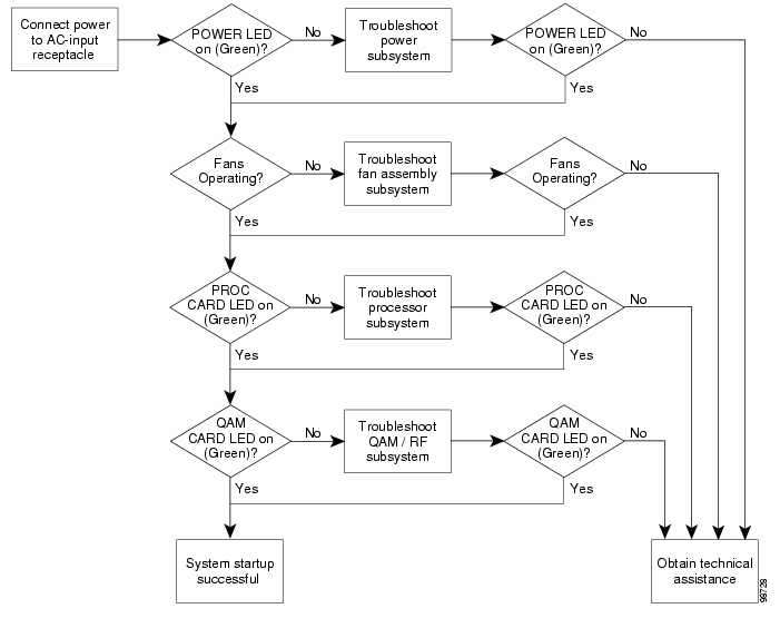
Figure 5-1 shows the general troubleshooting strategy described in this chapter. Refer to this chart, as necessary, to follow the steps to isolate problems to a specific subsystem.
Figure 5-1 General Troubleshooting Strategy for Startup Problems
Before You Call for Technical Assistance
If you are unable to solve the problem easily, contact a Cisco customer service representative for assistance and further instructions. (See Obtaining Technical Assistance, page xvi.)
Provide the representative with the following information:
•
•
•
•
•
•
•
Creating an Information Dump
It can be helpful to Technical Assistance if you prepare an information dump before contacting them. To create this information dump, do the following:
Step 1
Step 2
Step 3
uMG9820(debug)#infodump tftp://server-ip-address/filenameStep 4
Step 5
Solving Startup Problems by Using a Subsystems Approach
The key to solving problems with the system is isolating the problem to a specific subsystem. The first step in solving startup problems is to compare what the system is doing to what it should be doing.
Because a startup problem is usually caused by a single component, it is more efficient to isolate the problem to a subsystem rather than to troubleshoot each component in the system. For these troubleshooting procedures, consider the following subsystems:
•
•
•
•
Startup problems are commonly due to the source power or to a port adapter that is dislodged from the Cisco uMG9820. Although an overtemperature condition is unlikely at initial startup, the environmental monitoring functions are included in this chapter, because they also monitor internal voltages. (See More show Commands.)
Normal Startup Sequence
LEDs indicate all system states in the startup sequence. (See Front Panel LEDs, and Rear Panel Connectors and LEDs.) By checking the state of the LEDs, you can determine when and where the system failed in the startup sequence. Use the following descriptions to isolate the problem to a subsystem, and then proceed to the appropriate sections to try to resolve the problem.
When you start up the system, the following should occur:
1.
2.
a.
If this LED remains off when you start the Cisco uMG9820, then either there is a problem with the power supply (it is damaged or not connected correctly), or the processor card is not connected properly. Proceed to the discussion of the power subsystem in Subsystem Troubleshooting Tips.
b.
If this LED remains off when you start the Cisco uMG9820, or if this LED fails to turn green, proceed to the discussion of the fan assembly subsystem in Subsystem Troubleshooting Tips.
Caution
c.
d.
e.
If a QAM card LED for a slot in which there is a QAM card installed fails come on or to turn green, proceed to the discussion of the QAM/RF subsystem in Subsystem Troubleshooting Tips.
Subsystem Troubleshooting Tips
Troubleshooting Major Subsystems
Table 5-1 presents tips for troubleshooting the power, processor, QAM/RF module, and fan assembly subsystems.
Table 5-1 Subsystem Troubleshooting Tips
Power LED (POWER) is on.
No action is required.
Power source is good, power supplies are functional.
POWER LED is off.
1.
If cable is properly connected, suspect power source or cable. Proceed as follows.
2.
If new power source is used and POWER LED comes on, first source is faulty. If POWER LED still fails to come on, proceed to Step 3 for this subsystem.
3.
If the POWER LED comes on, the first cable is faulty. Return the faulty power cord to Cisco for replacement. If the POWER LED still fails to come on, proceed to Step 4 for this subsystem.
4.
The fuse has blown, is defective, or is not seated properly.
5.
One or both power supply modules may be faulty.
Processor LED (PROC CARD) is on and green.
No action is required.
Cisco uMG9820 has initialized successfully; system is operational.
PROC CARD LED is on and steady yellow.
1.
Steady yellow indicates a hardware failure. Proceed to Step 2 for this subsystem.
See More show Commands.
PROC CARD LED is on and flashing yellow.
2.
Flashing yellow indicates that the fan assembly microcontroller has not detected the heartbeat from the processor in the last 5 seconds. If this fails to clear the problem, proceed to Step 3 for this subsystem.
3.
QAM LED (QAM) is on and green.
No action is required.
Cisco uMG9820 has initialized successfully; system is operational.
QAM LED is off.
1.
If the power supply and fans appear operational and the QAM LED is off, the QAM card may be connected improperly. Proceed to Step 2 for this subsystem.
2.
If this fails, proceed to Step 5 for this subsystem.
QAM LED is on and yellow.
3.
A minimum of two QAM cards is required. If there are at least two cards, proceed to Step 4 and Step 5 for this subsystem.
4.
See More show Commands.
5.
If a QAM LED is either off or remains on and yellow, the system has detected a hardware failure in that specific card.
Airflow is noticeable; fans are moving. Power supply/fan assembly LED (PS/FAN) is on and green.
No action is required.
Fans are operating correctly, and the system has detected no faults.
TipFans are not moving.
1.
There is a problem with the fan or power.
Power supply/fan assembly LED (PS/FAN) is on and yellow.
2.
The system has detected a fault with one or both of the power supplies or the fan assembly. If this fails, proceed to Step 4 for this subsystem.
Power supply/fan assembly LED (PS/FAN) is on and flashing.
3.
If only one power supply is installed, green and yellow LEDs flash.
4.
Caution
Troubleshooting GE Ports
The following may be useful in helping to identify sources of error related to GE transport.
Polling Resources in Support of Failover
The microcontroller on the processor card detects whether an small form-factor pluggable (SFP) module is present in the GE ports. If an SFP module is present in a port, the processor card can then poll the SFP module to detect whether a fiber-optic cable has also been connected to that SFP module.
If the active GE port goes down, then the processor card checks the inactive port to see whether it has an SFP module and fiber-optic cable is attached. If so, the processor card activates that port and deactivates the port that went down.
As expected, if the inactive port is identified as not being ready to carry traffic (that is, both an SFP module and fiber-optic cable are not detected), then no failover switching takes place.
GE Port ALM LED Functionality
The MAC chip on the processor card detects PHY, CD, TX packet, and RX packet errors, as defined in the IEEE 802.3z standard. (The user cannot set the definitions and thresholds for these errors, as they are dictated by the standard.)
The MAC chip maintains a counter for the occurrence of each error type, and the microcontroller polls the MAC chip once per second. If any one of the counters is incremented, the ALM LED comes on.
If there is no change to any of the counters from the last time the counters were polled, then the ALM LED goes off. If any of the counters is incremented since the last time the counters were polled, the ALM LED remains on.
GE Port ERR LED Functionality
The microcontroller on the processor card maintains a bistate error flag for the TX and RX buffers. The occurrence of a TX buffer underrun or RX buffer overflow changes the state of the respective error flag to the "error" state. If the TX buffer or RS buffer returns to the expected operation, then the state of the respective flag is switched back to the no error state.
The microcontroller polls the TX buffer underrun and RX buffer overflow flags once per second (the same interval at which it polls the MAC chips). If the state of one or both error flags is in the error state, the ERR LED comes on.
If both error flags return to the no error state, the next time the flags are polled the ERR LED goes off. If either error flag is still in the error state the next time the flags are polled, then the ERR LED remains on.
Using CLI show Commands to Troubleshoot
This section presents resources for the following tasks:
•
The additional show commands are useful for environmental troubleshooting, as well as for retrieving software version and logging information,
Troubleshooting Ethernet Port and QAM Channels
In addition, "Product Overview," presents a variety of CLI show commands that are useful in troubleshooting GE and FE ports, as well as QAM channels.
More show Commands
A variety of additional show commands support the following tasks useful in troubleshooting:
•
•
•
•
Retrieving Environmental Status
Use the following environmental commands to see power, temperature, voltages, and fan (RPM) data, either singly or collectively:
show env alarms
uMG9820# show env alarmsUnder normal conditions, this command shows nothing. If there is one or more alarm state, this command shows one or more of the following:
Note
uMG9820-Proc > RTC Battery Voltage out of rangeuMG9820-Proc > GbE Mac Temperature out of rangeuMG9820-Proc > IXP CPU Voltage out of rangeuMG9820-Proc > FPGA Core Voltage out of rangeuMG9820-Proc > 12V Power Supply Voltage out of rangeuMG9820-Proc > 5V Power Supply Voltage out of rangeuMG9820-Proc > 3.3V Power Supply Voltage out of rangeuMG9820-Sys-AC > Midplane Temperature out of rangeuMG9820-Proc > IXP CPU Temperature out of rangeuMG9820-Proc > PCB Board Temperature out of rangeuMG9820-Proc > PCR FPGA Temperature out of rangeuMG9820-Proc > CAS FPGA Temperature out of rangeuMG9820-Fan > Fan #1 RPM out of rangeuMG9820-Fan > Fan #2 RPM out of rangeuMG9820-Proc > Fan #1 RPM out of rangeuMG9820-Proc > Fan #2 RPM out of rangeuMG9820-Sys-AC > Main Power Supply failureuMG9820-Sys-AC > Redundant Power Supply failureshow env all
uMG9820# show env alluMG9820-Fan > Fan #1 RPM : 2565uMG9820-Fan > Fan #2 RPM : 2610uMG9820-Proc > Fan #1 RPM : 5684uMG9820-Proc > Fan #2 RPM : 5595uMG9820-Proc > PCB Temperature : 50 CuMG9820-Proc > CPU Temperature : 51 CuMG9820-Proc > GbE Temperature : 47 CuMG9820-Sys-AC > Midplane Temperature : 24 CuMG9820-Proc > PCR FPGA Temperature : 43 CuMG9820-Proc > CAS FPGA Temperature : 46 CuMG9820-Proc > Main Voltage #1 : 12.06 VuMG9820-Proc > Main Voltage #2 : 5.13 VuMG9820-Proc > Main Voltage #3 : 3.19 VuMG9820-Proc > CPU Voltage : 1.94 VuMG9820-Proc > FGPA Voltage : 1.49 VuMG9820-Proc > Battery Voltage : 3.02 VAlarms : No Alarmsshow env fan
uMG9820# show env fanuMG9820-Fan > Fan #1 RPM : 2520uMG9820-Fan > Fan #2 RPM : 2565uMG9820-Proc > Fan #1 RPM : 5768uMG9820-Proc > Fan #2 RPM : 5591show env power
uMG9820# show env poweruMG9820-Proc > 12V Main Voltage : 11.96 VuMG9820-Proc > 5V Main Voltage : 5.13 VuMG9820-Proc > 3.3V Main Voltage : 3.19 VuMG9820-Proc > CPU Voltage : 1.94 VuMG9820-Proc > FGPA Voltage : 1.48 VuMG9820-Proc > Battery Voltage : 3.02 Vshow env temperature
uMG9820# show env temperatureuMG9820-Proc > PCB Temperature : 50 CuMG9820-Proc > CPU Temperature : 51 CuMG9820-Proc > GbE Temperature : 47 CuMG9820-Sys-AC > Midplane Temperature : 25 CuMG9820-Proc > PCR FPGA Temperature : 43 CuMG9820-Proc > CAS FPGA Temperature : 46 CRetrieving QAM Card and Cisco uMG9820 Software Versions
The following commands retrieve the software versions, respectively, of the QAM card and of the Cisco uMG9820 unit itself:
Note
show version
uMG9820# show versionShell v1.3.0Compiled 01-Apr-04 14:08 by root on beren 2.4.18-3 unknownuMG9820 SOFTWARE COMPONENT VERSION NUMBERS=====================================================================uMG9820-PROC BOOTLOADER IMAGE FILE : 0.0.12uMG9820-PROC KERNEL IMAGE FILE : 0.2.10uMG9820-PROC RAMDISK IMAGE FILE : 1.3.0uMG9820-PROC MICROCODE : 0441uMG9820-PROC FPGA 1 (PCR) FIRMWARE : 144uMG9820-PROC FPGA 2 (CAS) FIRMWARE : 002uMG9820-PROC PLD FIRMWARE : 07uMG9820-FAN COOLING MODULE MICROCODE : 0103uMG9820-QC42B 1 MICROCODE : 0.75ZuMG9820-QC42B 1 FPGA 256 QAM ANNEX B : 044uMG9820-QC42B 1 FPGA 64 QAM ANNEX B : 044uMG9820-QC42B 1 FPGA 256/64 QAM ANNEX A/C : RESERVED FOR FUTURE USEuMG9820-QC42B 1 FPGA Annex A/C COEFFICIENTS : RESERVED FOR FUTURE USEuMG9820-QC42B 2 MICROCODE : 0.75ZuMG9820-QC42B 2 FPGA 256 QAM ANNEX B : 044uMG9820-QC42B 2 FPGA 64 QAM ANNEX B : 044uMG9820-QC42B 2 FPGA 256/64 QAM ANNEX A/C : RESERVED FOR FUTURE USEuMG9820-QC42B 2 FPGA Annex A/C COEFFICIENTS : RESERVED FOR FUTURE USEuMG9820-QC42B 3 MICROCODE : 0.75ZuMG9820-QC42B 3 FPGA 256 QAM ANNEX B : 044uMG9820-QC42B 3 FPGA 64 QAM ANNEX B : 044uMG9820-QC42B 3 FPGA 256/64 QAM ANNEX A/C : RESERVED FOR FUTURE USEuMG9820-QC42B 3 FPGA Annex A/C COEFFICIENTS : RESERVED FOR FUTURE USEuMG9820-QC42B 4 MICROCODE : 0.75ZuMG9820-QC42B 4 FPGA 256 QAM ANNEX B : 044uMG9820-QC42B 4 FPGA 64 QAM ANNEX B : 044uMG9820-QC42B 4 FPGA 256/64 QAM ANNEX A/C : RESERVED FOR FUTURE USEuMG9820-QC42B 4 FPGA Annex A/C COEFFICIENTS : RESERVED FOR FUTURE USEuMG9820-QC42B 5 MICROCODE : 0.75ZuMG9820-QC42B 5 FPGA 256 QAM ANNEX B : 044uMG9820-QC42B 5 FPGA 64 QAM ANNEX B : 044uMG9820-QC42B 5 FPGA 256/64 QAM ANNEX A/C : RESERVED FOR FUTURE USEuMG9820-QC42B 5 FPGA Annex A/C COEFFICIENTS : RESERVED FOR FUTURE USEuMG9820-QC42B 6 MICROCODE : 0.75ZuMG9820-QC42B 6 FPGA 256 QAM ANNEX B : 044uMG9820-QC42B 6 FPGA 64 QAM ANNEX B : 044uMG9820-QC42B 6 FPGA 256/64 QAM ANNEX A/C : RESERVED FOR FUTURE USEuMG9820-QC42B 6 FPGA Annex A/C COEFFICIENTS : RESERVED FOR FUTURE USEuMG9820#show umg9820
uMG9820# show umg9820uMG9820-Sys-ACMidplane HW Revision : 6Chassis HW Revision : 2System Revision : 2System Cisco Serial Number : WAV12345678System Cisco Model Number : UMG9820-SYS-ACSystem Cisco Part Number : 74-3343-01GigabitEthernet MAC Address : 0050c206c0aaFastEthernet 0/1 MAC Address : 0050c206c31dFastEthernet 0/2 MAC Address : 0050c206c2a2uMG9820-QC42B #1Cisco Model Number : WQ20324Cisco CLEI Number : TBDCisco Serial Number : N/ACisco Part Number : N/AHardware Revision : 9MCU Revision : 0.75ZFPGA Revisions : 044:044:N/A:N/ANVRAM Revision : 3uMG9820-QC42B #2Cisco Model Number : WQ20324Cisco CLEI Number : TBDCisco Serial Number : N/ACisco Part Number : N/AHardware Revision : 9MCU Revision : 0.75ZFPGA Revisions : 044:044:N/A:N/ANVRAM Revision : 3uMG9820-QC42B #3Cisco Model Number : WQ20324Cisco CLEI Number : TBDCisco Serial Number : N/ACisco Part Number : N/AHardware Revision : 9MCU Revision : 0.75ZFPGA Revisions : 044:044:N/A:N/ANVRAM Revision : 3uMG9820-QC42B #4Cisco Model Number : WQ20324Cisco CLEI Number : TBDCisco Serial Number : N/ACisco Part Number : N/AHardware Revision : 9MCU Revision : 0.75ZFPGA Revisions : 044:044:N/A:N/ANVRAM Revision : 3uMG9820-QC42B #5Cisco Model Number : WQ20324Cisco CLEI Number : TBDCisco Serial Number : N/ACisco Part Number : N/AHardware Revision : 9MCU Revision : 0.75ZFPGA Revisions : 044:044:N/A:N/ANVRAM Revision : 3uMG9820-QC42B #6Cisco Model Number : WQ20324Cisco CLEI Number : TBDCisco Serial Number : N/ACisco Part Number : N/AHardware Revision : 9MCU Revision : 0.75ZFPGA Revisions : 044:044:N/A:N/ANVRAM Revision : 3uMG9820-FANCisco Serial Number : WAV07340097Cisco Model Number : UMG9820-FAN=Cisco CLEI Number : LFPQAFYHAACisco Part Number : 74-3344-01Hardware Revision : 3uMG9820-PROCCisco Serial Number : WAV073901JACisco Model Number : UMG9820-PROC=Cisco Part Number : 74-3345-01Cisco CLEI Number : LFCC380DAAHardware Revision : 6.04PCB Board Revision : 5aGbE Module #1Identifier : SFPConnector : RJ45Transceiver : 1000BASE-T DistanceMB/sEncoding : 8B10BNominal Bit Rate : 0 MbpsUpper Bit Rate Margin : 0%Lower Bit Rate Margin : 0%Length (50mm) : 0 mLength (62.5mm) : 0 mLength (copper) : 100 mVendor Name : Molex Inc.Vendor OUI : 00093aVendor PN : 74741-0001Vendor Rev : DVendor SN : 33371308GbE Module #2Identifier : SFPConnector : LCTransceiver : 1000BASE-SX, Intermediate Distance, Shortwave Laser w/o OFC, Multi-mode, 50/62.5mm, 100-200MB/sEncoding : 8B10BNominal Bit Rate : 2100 MbpsUpper Bit Rate Margin : 4%Lower Bit Rate Margin : 52%Length (50mm) : 300 mLength (62.5mm) : 150 mLength (copper) : 0 mVendor Name : PICOLIGHTVendor OUI : 000485Vendor PN : PL-XPL-00-S23-28Vendor Rev :Vendor SN : 313CD02XuMG9820#Retrieving ARP Table Information
The following command displays the complete Address Resolution Protocol (ARP) table with IP address, MAC address, resolution type, and interface information.
show arp
uMG9820-2> show arpProtocol Address Age (min) Hardware Addr Type InterfaceInternet 171.71.225.96 - 0000.0c07.ac01 ARPA FastEthernet0/1Internet 10.77.241.59 - 0000.0c07.ac01 ARPA FastEthernet0/1Internet 172.22.95.76 - 0800.208a.95f7 ARPA FastEthernet0/1uMG9820-2>Retrieving Entries in the Local Log File
The following command displays the entries in the current log file. The number-of-lines parameter determines the number of most recent log entries to be displayed.
show logging number-of-lines
uMG9820-2> show logging 25Aug 20 12:17:55 uMG9820-2 daemon.crit uMG9820-Proc[318]: Fan #2 RPM out of rangeAug 20 12:22:53 uMG9820-2 daemon.crit uMG9820-Proc[318]: PCR FPGA temperature out of rangeAug 20 12:24:10 uMG9820-2 daemon.crit uMG9820-Proc[318]: PCR FPGA temperature out of rangeAug 20 12:27:49 uMG9820-2 daemon.crit uMG9820-Fan[318]: Fan #1 RPM out of rangeAug 20 12:27:49 uMG9820-2 daemon.crit uMG9820-Fan[318]: Fan #2 RPM out of rangeAug 20 12:29:47 uMG9820-2 daemon.crit uMG9820-Fan[318]: Fan #1 RPM out of rangeAug 20 12:29:47 uMG9820-2 daemon.crit uMG9820-Fan[318]: Fan #2 RPM out of rangeAug 20 12:29:47 uMG9820-2 daemon.crit uMG9820-Proc[318]: Fan #1 RPM out of rangeAug 20 12:29:47 uMG9820-2 daemon.crit uMG9820-Proc[318]: Fan #2 RPM out of rangeAug 20 12:35:41 uMG9820-2 daemon.crit uMG9820-Fan[318]: Fan #1 RPM out of rangeAug 20 12:35:41 uMG9820-2 daemon.crit uMG9820-Fan[318]: Fan #2 RPM out of rangeAug 20 12:37:39 uMG9820-2 daemon.crit uMG9820-Fan[318]: Fan #1 RPM out of rangeAug 20 12:37:39 uMG9820-2 daemon.crit uMG9820-Fan[318]: Fan #2 RPM out of rangeAug 20 12:37:39 uMG9820-2 daemon.crit uMG9820-Proc[318]: Fan #1 RPM out of rangeAug 20 12:37:39 uMG9820-2 daemon.crit uMG9820-Proc[318]: Fan #2 RPM out of rangeAug 20 12:39:42 uMG9820-2 daemon.crit uMG9820-Fan[318]: Fan #1 RPM out of rangeAug 20 12:39:42 uMG9820-2 daemon.crit uMG9820-Fan[318]: Fan #2 RPM out of rangeAug 20 12:41:42 uMG9820-2 daemon.crit uMG9820-Fan[318]: Fan #1 RPM out of rangeAug 20 12:41:42 uMG9820-2 daemon.crit uMG9820-Fan[318]: Fan #2 RPM out of rangeAug 20 12:41:42 uMG9820-2 daemon.crit uMG9820-Proc[318]: Fan #1 RPM out of rangeAug 20 12:41:42 uMG9820-2 daemon.crit uMG9820-Proc[318]: Fan #2 RPM out of rangeAug 20 12:44:18 uMG9820-2 daemon.crit uMG9820-Proc[318]: PCR FPGA temperature out of rangeAug 20 12:48:54 uMG9820-2 daemon.err uMG9820-Proc[318]: Gigabitethernet device 1 link downAug 20 12:48:59 uMG9820-2 daemon.notice uMG9820-Proc[318]: Gigabitethernet device 1 link upAug 20 12:50:42 uMG9820-2 user.info commandline[8627]: show logginguMG9820-2>
![]()
![]()
![]()
![]()
![]()
![]()
![]()
![]()
Posted: Fri Oct 8 10:25:03 PDT 2004
All contents are Copyright © 1992--2004 Cisco Systems, Inc. All rights reserved.
Important Notices and Privacy Statement.