|
|

Table Of Contents
Information About Subscriber Manager Fail-Over
Database Duplication Recovery Management
Subscriber Manager Fail-Over
This module describes topics that are related to using the Subscriber Manager together with clusters and redundancy.
As the Subscriber Manager plays a critical role in the Cisco SCA BB solution that is deployed in tier-one service provider environments, it also supports, starting with SM version 2.2, a fail-over operational mode. This feature minimizes system downtime that is caused by SM failure (as further discussed in Information About Subscriber Manager Fail-Over ).
This section introduces various concepts that are related to using a cluster of two SM nodes in a fail-over operational mode.
Note
For the purposes of this section, it is assumed that the reader is familiar with the Veritas Cluster technology.
Information About Subscriber Manager Fail-Over
•
Overview
The fail-over scheme that is implemented in the SM is based on the Veritas cluster technology. The cluster includes two machines, each of them running SM TimesTen and Veritas software. The Veritas Cluster Server (VCS) software consolidates the SMs and exposes a single entity by providing a single virtual IP address for the entire cluster.
The cluster software distinguishes an active and a standby machine: the active machine "owns" the virtual IP address and all network connections, while the standby machine is passive until a fail-over occurs. At fail-over, the IP address is passed from the failing server to the backup server, which becomes activated and re-establishes all network connections.
When a fail-over occurs, the LEGs lose their connection with the failed SM, and reconnect to the activated (backup) SM and retransmit their uncommitted messages. The activated SM connects to the SCE platforms and performs an SCE resynchronization.
The TimesTen database replication agent constantly replicates the SM database from the active node to the standby node. This enables a fast fail-over from one SM to another, since the subscriber data in the activated machine is always valid. The two SM nodes do not communicate except for passing the subscriber data.
The VCS uses software components called "cluster agents" to monitor and control the state of resources such as Network Interface Cards (NICs), disks, IP addresses, and processes. Cisco supplies cluster agents to monitor the SM and the TimesTen database daemon and replication agent.
As part of the cluster operation, the TimesTen database daemon and replication agents are up and running regardless of the fail-over state. The SM Veritas agent monitors the daemon and the replication agent process. In case one of them fails, a fail-over takes place.
Note
The following sections describe these concepts in further detail.
Normal Operation
The two SM nodes operate in hot-standby mode, where at any given time one node (the active node) receives and processes all the SM events, while the other node (the standby node) waits and is ready to go into operation on fail-over. For enabling seamless fail-over and for minimizing the fail-over time, the two SM nodes operate without an external storage device.
During the normal operation of the cluster, the active node (selected by the cluster):
•
•
•
On the standby node, both the SM and the TimesTen software are running:
•
•
•
Fail-Over Topology
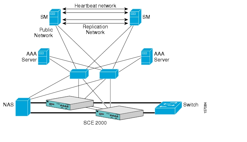
The following figure depicts an SM cluster configuration in a topology with a redundant AAA server and two SCE 2000 platforms that are cascaded for redundancy.
Figure 3-1 SM Cluster Configuration for Fail-Over Topology
As already mentioned, an SM fail-over topology includes two SM nodes connected in a cluster scheme.
Two dedicated (private) redundant networks interconnect the two nodes:
•
•
The two nodes should be located in the same site, where the heartbeat network is implemented using back-to-back connectivity between the two nodes or via redundant switches. Each node in the cluster has redundant network paths (NICs) connecting it to all of the external entities with which the SM communicates (AAA, LEG, SCE).
Each node in the cluster has a minimum of six Ethernet NICs, where:
•
•
•
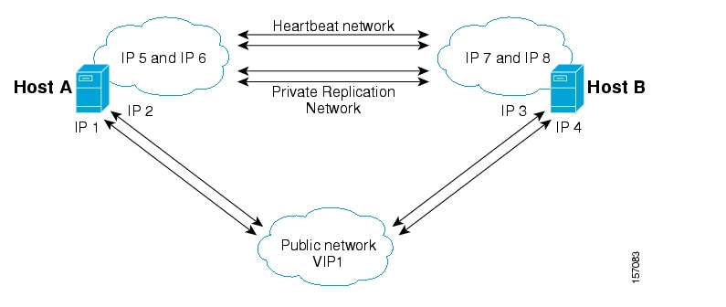
The cluster has a virtual IP (VIP) address used for communication with the external entities. Each node in the cluster has also an IP address for administration of the node/cluster, as well as an IP address for replication use.
Upon failure of the primary NIC of the public network, there is a fail-over to the secondary NIC on the same node, keeping the same IP addresses (VIP1), with no fail-over of the cluster. Upon failure of the primary NIC of the replication or heartbeat networks, there is fail-over to the secondary NIC on the same node, keeping the same IP addresses (VIP2 and VIP3), with no fail-over of the cluster.
The following diagram illustrates the usage of the regular and virtual IP addresses used in cluster configuration:
•
•
Figure 3-2 Regular and Virtual IPs in Cluster Configuration
For further information about replication IP configuration, see Veritas Cluster Server.
Fail-Over Operation
During normal operation, the Veritas Cluster Server mechanism automatically selects one of the SM servers to be active and the other to be standby.
The active SM server performs all the normal SM functionality. The two servers maintain the heartbeat mechanism between them, and the active server continuously replicates the subscriber database to the standby server's database.
The standby SM server acts as a hot-standby machine, so it is completely ready for taking over (becoming activated) in a minimal fail-over time.
The following types of failures trigger the fail-over mechanism:
•
•
•
•
Note
After detecting a failure, the standby SM becomes activated, and the following occurs:
•
•
•
•
How to Recover from Fail-Over
Different types of failures require different triggering for the recovery procedure. Some failures may recover automatically such as intra-node ports link-failure, which recovers automatically when the link revives, while others may need manual intervention.
Recovery may take place when an SM that experienced a failure is self-recovered or after it was replaced (if needed). The purpose of the recovery procedure is to take the cluster back to a fully functional mode. When the recovery procedure ends, the behavior is the same as it was after installation.
The failed SM server is recovered manually or automatically, according to the type of failure that occurred. The recovery procedures, and when they are used, are described in the following sections.
•
•
Machine Reboot
Recovering from a machine reboot is a fully automatic recovery process, where the failed SM server reboots, and after establishing a connection with the other server and synchronizing the databases, the cluster of the two SM servers is ready again for fail-over operation.
Note
Step 1
Step 2
Step 3
Step 4
Step 5
The SM in the recovered server is ready after the database recovery process is running and the SM moves from Init state to Standby state.
Replacing the Server
Replacing the server is necessary when the machine has an unrecoverable physical failure. A new machine that is installed with fresh SM, TimesTen, and VCS installations replaces the server.
Replacing the server is a manual recovery, where the failed SM server is physically replaced. After connecting the new SM server to the network, configuring it and synchronizing the two databases, the cluster of the two SM servers is ready again for fail-over operation.
Step 1
Step 2
Step 3
Use the following CLU command if you need to copy only the p3sm.cfg file:
p3sm --load-config --remote= NEW-SM_IPStep 4
See Database Duplication Recovery.
Step 5
Step 6
The SM in the recovered server is ready after the database recovery process is completed and the SM moves from Init state to Standby state.
Database Duplication Recovery
Database duplication recovery is a manual recovery, which is needed when the standby node database loses synchronization with the active node database. Loss of synchronization can occur when one of the SM machines is replaced or when the replication process on the active node fails to replicate all of the data inserted to its database (replication NICs were disconnected).
Step 1
Use the VCS CLU hastop -localcommand to stop the VCS.
Step 2
Use the CLU command p3sm --stop.
Step 3
Use the CLU command p3db --rep-stop.
Step 4
Use the CLU command p3db --destroy-rep-db.
Step 5
Use the CLU command p3db --duplicate.
Step 6
Use the VCS CLU hastartcommand), which will automatically start the replication process and the SM.
Database Duplication Recovery Management
The two SM servers are configured using Command-Line Utilities and a configuration file (see Configuration and Management and How to Configure a Subscriber Management Solution ). The actual configuration is performed for the active SM and then manually replicated for the standby SM.
SUMMARY STEPS
1.
2.
3.
4.
5.
6.
DETAILED STEPS
Step 1
Step 2
Copy the configuration file from ~pcube/sm/server/root/config/p3sm.cfg on the active node to the standby node, and apply the SM configuration file by using the CLU command p3sm --load-config.
Alternatively, you can replicate the SM configuration file to the standby machine by running the CLU command p3sm --load-config --remote=NEW-SM_IP
Step 3
Step 4
Use the CLU command p3inst --install -f PQI file path.
Step 5
If you have made changes in the database-related configuration files, copy the files to /etc/system (for Solaris) or to /etc/sysctl.conf (for Linux), and /var/TimesTen/sys.odbc.ini from the active node to the standby node.
Note
Note
Step 6
Notifications are enabled through SNMP traps that the Veritas Cluster Server provides. The Veritas Cluster Server supports SNMP traps such as:
•
•
•
![]()
![]()
![]()
![]()
![]()
![]()
![]()
![]()
Posted: Wed Aug 15 17:43:37 PDT 2007
All contents are Copyright © 1992--2007 Cisco Systems, Inc. All rights reserved.
Important Notices and Privacy Statement.