cc/td/doc/product/cable/svc_ctrl/sceng2
hometocprevnextglossaryfeedbacksearchhelp
PDF

Table Of Contents

Connect the Power Supply Units

Connect the Chassis Ground

Connecting the Power

Connect the DC-Input Power Supply Unit

Connect the AC-Input Power Supply Unit


Connect the Power Supply Units


This section provides information for grounding the SCE 2000 platform and connecting the AC or DC power supply units.

Connect the Chassis Ground 

Connecting the Power 

Connect the Chassis Ground

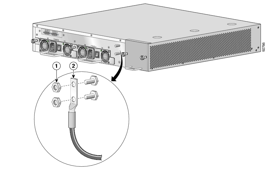
Figure 3-1 Grounding the Unit (AC)

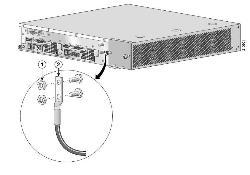
Figure 3-2 Grounding the Unit (DC)

A Grounding kit is provided with each SCE 2000 . Use this Grounding kit to properly ground the SCE 2000 chassis.

When installing the unit, the chassis ground connection must always be made first and disconnected last.


Step 1 On the rear panel of the SCE 2000 , locate the chassis grounding connector (refer to the appropriate figure for an AC- or DC-powered SCE 2000 above).

Step 2 Attach the grounding cable (green and yellow colored cable), firmly fastening the (enclosed) hex nuts and spring washers with a #ј" hex wrench (refer to the appropriate figure for an AC- or DC-powered SCE 2000 above).

The other side of the grounding cable must be connected to the site equivalent of the AC earth.


Connecting the Power

The following sections describe how to reconnect the AC or DC power:

Connect the DC-Input Power Supply Unit 

Connect the AC-Input Power Supply Unit 

Connect the DC-Input Power Supply Unit

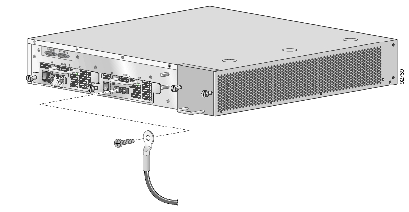
Figure 3-3 Connecting the DC Power

Before completing any of the following steps, and to prevent short-circuit or shock hazards, ensure that power is removed from the DC circuit. To ensure that all power to the power supply unit is OFF, locate the circuit breaker on the panel board that services the DC circuit, switch the circuit breaker to the OFF position, and tape the switch handle of the circuit breaker in the OFF position.

Wiring should be done by a professional in accordance with state and local electrical codes.


Step 1 Ensure that the DC power line input leads are disconnected from the power source.

Step 2 Using the number 2 Phillips screwdriver, remove the protective plate from the terminal block.

Step 3 Insert one receptacle screw into the hex or loop connector on one power line input, insert the screw with the connector into the corresponding lead receptacle and tighten the receptacle screw using the number 2 Phillips. Repeat for the remaining power line input lead.


Note The color coding of the DC-input power supply leads depends on the color coding of the DC power source at your site. Make certain the lead color coding you choose for the DC-input power supply matches lead color coding used at the DC power source.


Note Use 12 AWG (2.5 mm) copper wire only with hex or loop connectors. Ring terminals must be UL approved and suitable for 12 AWG wire.


Step 4 Using the number 2 Phillips screwdriver, securely fasten the protective plate to the terminal block.

Step 5 Connect the DC power line input leads to the DC power source through a fast 10A circuit breaker.

Step 6 Turn the on/off switch to the on position.

Step 7 Look at the IN and OK LEDs on the power supply unit and the corresponding Power LED on the front panel. If the DC-input power supply unit is operating properly, these LEDs will be glowing green.

Step 8 Ensure that the power supply is properly aligned and the installation screw is tightened.


Connect the AC-Input Power Supply Unit


Step 1 Plug the AC-input power cable into the AC-input power receptacle on the AC-input power supply

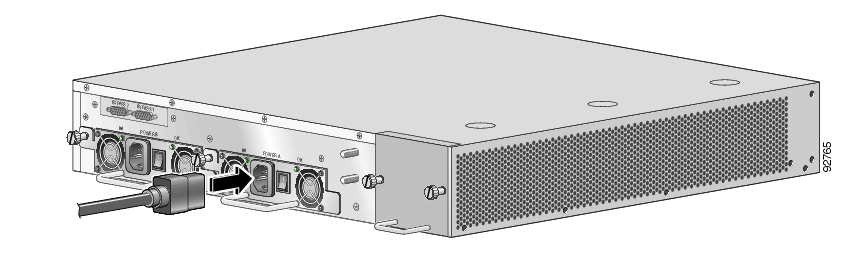
For AC-input power, we recommend powering the SCE 2000 platform from a 120 VAC, 15A receptacle U.S. (240 VAC, 10A international) at the power source.

Figure 3-4 Connecting the AC Power

Step 2 Plug the AC power supply cable into the AC power source.

Step 3 Turn the on/off switch to the on position.

Step 4 Look at the IN and OK LEDs on the power supply unit and the corresponding Power LED on the front panel. If the AC-input power supply unit is operating properly, these LEDs will be glowing green.

Step 5 Ensure that the power supply is properly aligned and the installation screw is tightened.


hometocprevnextglossaryfeedbacksearchhelp

Posted: Thu May 31 02:17:18 PDT 2007
All contents are Copyright © 1992--2007 Cisco Systems, Inc. All rights reserved.
Important Notices and Privacy Statement.