|
|

Table Of Contents
Single Link: Receive-only Topology
Dual Link: Single SCE 2000 Topologies
Dual Link: Two SCE 2000s Topology
Configuring GigabitEthernet Auto-Negotiation
Connect the GBE Line Interface Ports
Cable the Line Ports
This section provides instructions for cabling the Gigabit Ethernet ports for both one and two SCE 2000 topologies, and for configuring Gigabit Ethernet (GBE) interface parameters. In a topology utilizing two SCE 2000s (cascade), this includes the cascade ports as well as the line ports.
Class 1 laser. Avoid exposure to radiation and do not stare into open aperture.
Note
When installing a cascaded system, it is extremely important to follow the sequence of procedures outlined in the section Installing a Cascaded System.
•
•
Information About Cabling
Note
•
•
•
•
Single Link: Inline Topology
In the inline topology, the SCE 2000 resides physically on the GBE (Gigabit Ethernet) link between the subscribers, which are usually connected through either a BRAS (in DSL access), a PDSN (in wireless access), a CMTS (in the Cable access), or a switch or router aggregator (in other topologies), and the network, where the SCE 2000 usually connects to a router or layer 3 switch network element.
Figure 5-1 Cabling Diagram for Single Link Inline Topology
In the single link inline topology, either the first GBE link (first two ports) of the SCE 2000or the second GBE link (third and fourth ports) can be used, as illustrated in the diagram above. The remaining pair of ports is unused.
Either port 1 or port 3 is used for connecting to the network element that is deployed on the subscriber side of the SCE 2000 while port 2 or port 4 is used for connecting to the network element that is deployed on the network side of the SCE 2000.
Inline topology requires both Receive and Transmit fibers
Single Link: Receive-only Topology
In this topology, an optical splitter resides physically on the GBE link that the SCE 2000 should monitor. The optical splitter is connected to the SCE 2000 via Rx links only.
In this topology, the traffic passes through the optical splitter, which splits traffic to the SCE 2000.
Note
Figure 5-2 Cabling Diagram for Single SCE Platform Single Link Receive-only Topology
The single link receive-only topology cabling is similar to that for single link inline, in that either the first GBE link (first two ports) or the second GBE link (third and fourth ports) can be used, as illustrated in the diagram above. The remaining pair of ports is unused.
Either port 1 or port 3 is used for connecting to the network element that is deployed on the subscriber side of the SCE 2000 while port 2 or port 4 is used for connecting to the network element that is deployed on the network side of the SCE 2000.
Dual Link: Single SCE 2000 Topologies
In this topology, one SCE 2000 is connected to two full duplex, GBE links. The SCE 2000 may be either inline, to support both monitoring and traffic control functionality, or receive-only for traffic monitoring functionality only.
When one SCE 2000 supports two links, the first two ports are connected to one link, while ports 3 and 4 are connected to the second link as follows;
•
•
•
•
As with the single link cabling, inline topologies require both Receive and Transmit fibers, while Receive-only systems use only Receive fibers.
Note
The following two diagrams illustrate the connections for dual links, with a single SCE 2000 deployed for both inline and receive-only topologies.
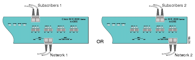
Figure 5-3 Cabling Diagram: Dual Link One SCE Platform Inline
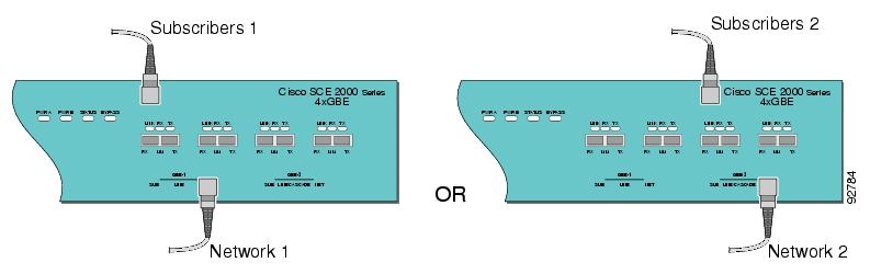
Figure 5-4 Cabling Diagram: Dual Link One SCE Platform Receive-only
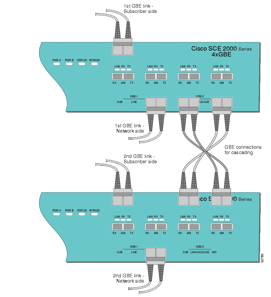
Dual Link: Two SCE 2000s Topology
In this topology, two SCE 2000s are connected to two full duplex, GBE links, providing full redundancy through cascading the two SCE 2000s. The SCE 2000s may be either inline, to support both monitoring and traffic control functionality, or receive-only for traffic monitoring functionality only.
Note
Note
When two SCE 2000s are used, the first two ports in each SCE 2000 are connected to the links, while ports 3 and 4 are the cascade ports that are used for communicating between the two SCE 2000s as follows:
SCE 2000 #1
•
•
•
•
SCE 2000 #2
•
•
•
•
Note
Inline topologies require connecting both Receive and Transmit fibers to the SCE 2000. Cascade ports always require both Receive and Transmit fibers to be connected.
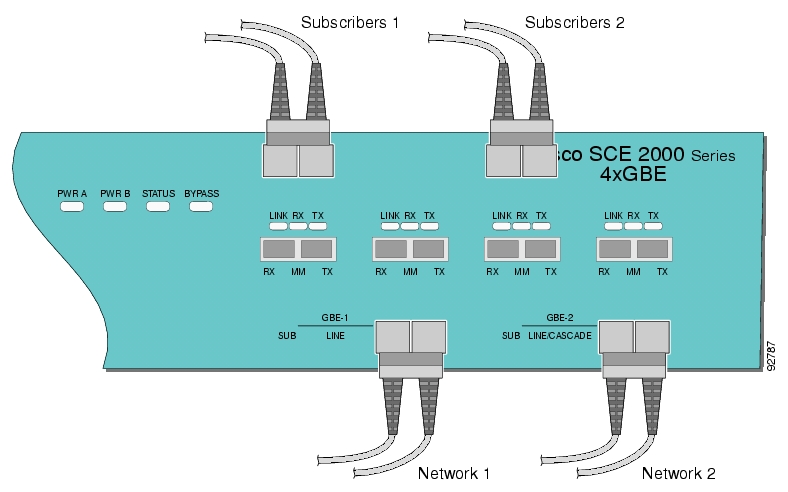
The following diagram illustrates the connections for a dual link, two SCE 2000 inline topology
Figure 5-5 Cabling Diagram: Dual Link Inline Topology Two Cascaded SCE Platforms
Configuring GigabitEthernet Auto-Negotiation
By default, the SCE 2000 GBE line interface ports are configured with auto-negotiation disabled.
Note
Note
Step 1
configure, and press Enter.Enters the Global Configuration Mode.
Step 2
interface GigabitEthernet 0/portnumber, and press Enter.- where portnumber is the number of the selected port (1-4).
Enters the GigabitEthernet Interface configuration mode for the specified GBE port.
Step 3
auto-negotiateand press Enter.Enables auto-negotiation for the GBE interface.
Step 4
exitand press Enter.Returns to Global Configuration Mode, from which you can enter the GigabitEethernet Interface configuration mode for the remaining GBE ports.
Step 5
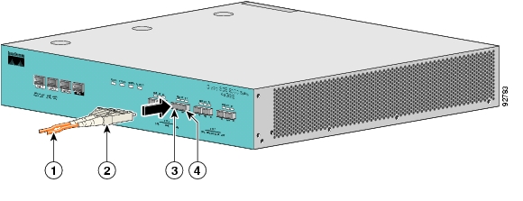
Connect the GBE Line Interface Ports
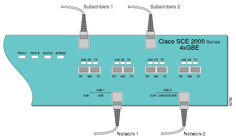
Figure 5-6 Cabling the GBE Interface
The following table presents the fiber specifications. The SCE 2000 may be ordered with either Multimode or Single Mode transceivers The transceiver type is indicated on the front panel under the ports. Note that both transceivers on any individual SCE 2000 are the same, either 850nm Multimode OR 1310nm Single Mode.
Step 1
Step 2
If the link LED does not light, try removing the network cable plug and reinserting it firmly into the module socket.
![]()
![]()
![]()
![]()
![]()
![]()
![]()
![]()
Posted: Thu May 31 02:16:54 PDT 2007
All contents are Copyright © 1992--2007 Cisco Systems, Inc. All rights reserved.
Important Notices and Privacy Statement.