|
|

This chapter explains the procedures to install and connect the Cisco 6920. The chapter contains the following sections:
The rack-mount brackets on the Cisco 6920 are for mounting in standard, 19-inch wide, 4-post equipment racks. The rack-mount brackets are not suitable for use with other racks, such as 23-inch telco racks.
To assist you with your installation and to provide an historical record of what was done, by whom, use the checklist in Table 3-1. Make a copy of this checklist and indicate when each procedure or verification is completed. When the checklist is completed, place it in your site log (see Appendix A, "Site Log") along with the other records for your new Cisco 6920.
| Task | Verified by | Date |
|---|---|---|
Cisco 6920 and all accessories unpacked |
|
|
Types and numbers of interfaces ordered verified as installed in chassis |
|
|
Cisco 6920 mounted in rack |
|
|
Cable-management brackets installed (optional but recommended) |
|
|
Power cables connected to power sources and Cisco 6920; cables secured |
|
|
Captive installation screws on PowerPC, I/O, and input cards checked |
|
|
Video interface cables and devices connected |
|
|
System power turned on (Power LED on front panel is on) |
|
|
PowerPC, I/O, input, and DSP cards operational (enabled LEDs on the cards are on) |
|
|
When you receive your Cisco 6920, use the following procedure to check the contents of the shipping container. Use the Cisco 6920 Installation Checklist (see Table 3-1) and the Cisco 6920 Component List (see Table 3-2) to ensure that you received all the components you ordered.
| Component | Description | Received |
|---|---|---|
Chassis | Cisco 6920 chassis configured with a PowerPC card, one AC-input power supply, one or more I/O cards, input cards (if ordered) Note Blank cards (faceplates) should be installed in empty card slots. |
|
AC-input power cables | Modular power cable |
|
Ethernet cable | Shielded RJ-45 to RJ-45 (straight-through) |
|
Documentation | Quick Start Guide for the Cisco 6920 RateMux Multiplexer Regulatory Compliance and Safety Information for the Cisco 6920 RateMux Multiplexer Documentation Guide for the Cisco 6920 RateMux Multiplexer |
|
 |
Note Do not discard the shipping container. You will need the container if you move or ship your Cisco 6920 in the future. |
Step 1 Verify that the following are included in the shipping container (the accessories box might be separate):
Step 2 Check the contents of the accessories box against the Cisco 6920 Component List and the packing slip to verify that you received all listed equipment, which should include the following;
|
Note A 12-foot triple-shielded straight-through Ethernet cable is included. This cable must be used for FCC compliance. |
Step 3 Verify that the input/output cards and the input cards installed in your Cisco 6920 match the types on the packing list.
Step 4 Review Appendix A, "Site Log," then go to the "General Installation" section to begin the installation.
 |
Warning To prevent bodily injury when mounting or servicing this unit in a rack, you must take special precautions to ensure that the system remains stable. The following guidelines are provided to ensure your safety: |
To see translations of the warnings that appear in this publication, refer to the Regulatory Compliance and Safety Information document that accompanied this device.
|
Note Be sure to leave enough room above and below the Cisco 6920 for airflow. |
To install the chassis in the equipment rack:
Step 1 On the chassis, ensure that all captive screws on the PowerPC card, I/O cards, input cards, and power supply are tightened.
Step 2 Make sure that your path to the rack is unobstructed. If the rack is on wheels, ensure that the brakes are engaged or that the rack is otherwise stabilized.
 |
Tip Two people should perform Step 3 through Step 6. |
Step 3 Position the chassis so that the front end is closest to you; then lift the chassis from both sides and move it to the rack. To prevent injury, avoid sudden twists or moves.
Step 4 Slide the chassis into the rack, pushing it back until the brackets installed at the front of the chassis meet the mounting strips or posts on both sides of the equipment rack.
|
Tip The rack-mount bracket must be placed behind the rack post or mounting strip in the rear installation configuration. |
Step 5 While keeping the brackets flush against the posts or mounting strips, position the Cisco 6920 so that the holes in the brackets are aligned with those in the mounting strips.
Step 6 Insert all four 10/32 x 3/8-inch slotted screws (two on each side) through the brackets and into the mounting strip (use the top and bottom bracket holes. Using a 7/16-inch, flat-blade screwdriver, tighten all the screws.
This completes the procedure for installing the chassis in the rack. Proceed to the "Cabling" section to continue the installation.
This section provides information on connecting your PC or laptop, the LAN, and video cables to your Cisco 6920.
There are three primary ways to access the Cisco 6920. Each has a different purpose.
1. The serial connection uses HyperTerminal and is required when the IP address of the Cisco 6920 is unknown.
2. Connect.exe is an application file included with the Cisco 6920 software bundle. It uses Ethernet and requires an IP address to connect. Connect.exe allows access to the diagnostic menus similar to those seen when using HyperTerminal. Connect.exe is primarily used for software upgrades and environmental parameter changes.
3. Web-based configuration requires an Ethernet connection and uses Netscape Communicator or Microsoft Internet Explorer to connect to the Cisco 6920 using its IP address. The browser connects to the RateMux Manager GUI and is the usual mode for configuring and monitoring the Cisco 6920.
The following sections provide details on how to connect to the Cisco 6920 using each of the three methods.
|
Tip If the IP address is unknown, you can try the default address 10.0.0.200. |
Connect a regular 9-pin serial cable from the serial communications port of the connecting computer to the debug connector on the PowerPC card in the Cisco 6920. This is a straight-through cable, also referred to as an extension serial cable.
|
Note Do not use a null modem cable or you will not be able to connect. |
Step 1 Configure a HyperTerminal session for the following: 57,600, 8 bits, no parity, 1 stop bit,
flow control = none.
Step 2 Power on the Cisco 6920 and use the Call option in HyperTerminal to start the session within 10 seconds.
Step 3 After starting the session, press Enter on the connecting computer until the Cisco 6920 screen dump appears (5 to 60 seconds) and the IP address of the Cisco 6920 is visible.
Step 4 While connected in HyperTerminal, you can change the IP address and the name of the Cisco 6920.
Step 1 Connect to the Cisco 6920 using HyperTerminal or connect.exe.
Step 2 From the menu, choose C Environmental Parameters and FLASH Partitions.
Step 3 Choose B Environmental Parameters.
Step 4 Choose B Change Environmental Parameters.
Step 5 You will be prompted for each parameter. Press Enter to skip any parameters that do not need to be changed. When the IP Address parameter appears, enter the new IP address and press Enter.
Step 6 After skipping over the remaining options, press S then press Enter to save the changes.
Step 7 Power cycle the Cisco 6920 and use the new IP address.
Step 1 Follow Step 1 through Step 5 above for changing the IP address.
Step 2 When the Host Name option appears, enter the new name.
Step 3 After skipping over the remaining options, press S then press Enter to save the changes.
Step 4 Power cycle the Cisco 6920.
Step 1 If the Cisco 6920 IP address is unknown, use HyperTerminal to find it.
Step 2 Make sure that the connecting computer's IP domain matches that of the Cisco 6920.
Step 3 Connect an Ethernet cable from the Cisco 6920 to the connecting computer. Use a crossover cable if you are connecting directly.
|
Note Shielded Ethernet cables must be used for FCC compliance. |
Step 4 Locate the application file connect.exe included in the software bundle and launch it.
Step 5 Click Connection on the pull-down menu, then click connect.
Step 6 Enter the Cisco 6920 IP address in the window. Don't click OK.
Step 7 Power on the Cisco 6920. Within 10 seconds, click OK. Connection should occur in 5 to 60 seconds.
Step 1 If the Cisco 6920 IP address is unknown, use HyperTerminal to find it.
Step 2 Make sure that the connecting computer's IP domain matches that of the Cisco 6920.
Step 3 Connect an Ethernet cable from the Cicso 6920 to the connecting computer. Use a crossover cable if you are connecting directly.
|
Note Shielded Ethernet cables must be used for FCC compliance. |
Step 4 If the Cisco 6920 is not running, power it on and wait for 3 to 5 minutes for it to initialize.
Step 5 Launch Netscape or Microsoft Internet Explorer and enter the Cisco 6920 IP address. The RateMux Manager GUI appears.
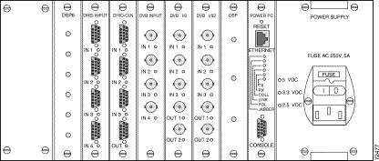
There are two industry standard types of video transport stream connectors, those for DVB-ASI boards and those for DHEI boards.
To connect the video transport I/O streams, attach the input DVB-ASI or DHEI cables to the respective connectors on the back panel of the Cisco 6920, as shown in Figure 3-1.
|
Note The DHEI I/O cards get their output clock signal from the DHEI IN1 port on the DHEI I/O card. |
|
Warning Care must be given to connecting units to the supply circuit so that wiring is not overloaded. To see translations of the warnings that appear in this publication, refer to the Regulatory Compliance and Safety Information document that accompanied this device. |
|
Warning Never defeat the ground conductor or operate the equipment in the absence of a suitably installed ground conductor. Contact the appropriate electrical inspection authority or an electrician if you are uncertain that suitable grounding is available. To see translations of the warnings that appear in this publication, refer to the Regulatory Compliance and Safety Information document that accompanied this device. |
|
Note Cards in the Cisco 6920 chassis are not hot-swappable. The Cisco 6920 must be powered down before cards are removed and replaced. |
Following are the procedures for connecting AC-input to your Cisco 6920.
Step 1 At the rear of the Cisco 6920, check that the power switch on the power supply is in the OFF (0) position.
Step 2 Plug the AC power supply cable into the AC power source.
After installing your Cisco 6920 and connecting cables, power on the Cisco 6920 as follows:
Step 1 Check for the following:
Step 2 At the rear of the Cisco 6920, place the power switch on the power supply in the ON (|) position. The green Power On LED on the power supply should be on.
![]()
![]()
![]()
![]()
![]()
![]()
![]()
![]()
Posted: Fri Sep 27 00:19:29 PDT 2002
All contents are Copyright © 1992--2002 Cisco Systems, Inc. All rights reserved.
Important Notices and Privacy Statement.