|
|

This chapter contains step-by-step instructions for configuring and controlling the Cisco 6920 using the RateMux Manager. The chapter contains the following sections:
The RateMux Manager is a web-based user interface that allows you to configure and control the Cisco 6920. Start up the Cisco 6920 by powering up the unit; then launch an Internet browser from your PC. Use the Internet browser to access and use the RateMux Manager web server, which runs in the memory of the PowerPC module of the Cisco 6920.
 |
Note Make sure that the Cisco 6920 is properly installed with all cables connected. Then turn on the Cisco 6920 and wait at least 30 seconds before proceeding. See Chapter 3, "Installing the Cisco 6920," for more information. |
 |
Note Configuration can also be performed using Simple Network Management Protocol (SNMP). See Appendix B, "SNMP Operations," for more information. |
The RateMux Manager runs on a web browser. Start by launching a web browser such as Netscape Communicator or Microsoft Internet Explorer on your computer.
A unique IP address is assigned to each PowerPC module. This IP address is printed on a label on the Cisco 6920. Your web browser uses this address to communicate exclusively with the Cisco 6920 with the corresponding IP address.
To access the RateMux Manager, enter the preassigned IP address in the web browser.
 |
Note For Netscape Communicator Users: Enter the Cisco 6920 RateMux multiplexer IP address in the line LOCATION. For Microsoft Internet Explorer Users: Enter the Cisco 6920 IP address in the line LOCATION/URL. |
 |
Note It is also possible to boot the Cisco 6920 dynamically off the network. Refer to Appendix C, "Configuration Notes," for further information. |
 |
Note This version of the product does not support Reverse Address Resolution Protocol for automatic assignment of Internet addresses. Cisco recommends using a direct Internet connection as opposed to a proxy server. If your proxy server caches responses from the Cisco 6920, this might yield inaccurate responses. |
Step 1 Enter the preinstalled IP address in the Location/URL field of your browser and press Enter.
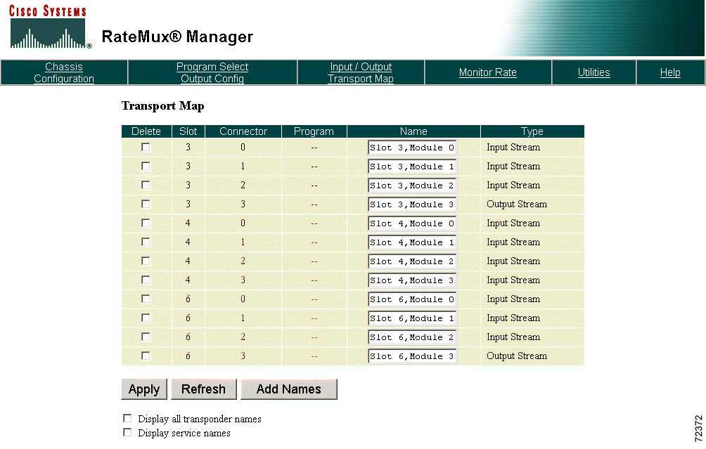
After a connection is successfully established with the Cisco 6920, the Transport Map appears (see Figure 4-1).
 |
Note If security features have been configured, a display appears asking for a user name and password. This optional configuration feature is implemented using the connect.exe program. Refer to Appendix C, "Configuration Notes," for further information. |
 |
Note The time required for the Cisco 6920 to boot, and for the initial connection to be established, depends on the number of cards installed in the chassis. The higher the number of cards installed, the longer it takes. |
 |
Note If the web browser indicates that it cannot find the IP address you have entered, verify that you are entering the correct IP address for your network. |
The RateMux Manager is loaded into your PC from memory, displaying the most recently saved configuration.
Step 2 From the Edit menu of the browser, choose Preferences. The Preferences dialog box appears.
Step 3 With the Cisco 6920 address displayed in the Location field of the Home page panel, click Use Current Page.
Step 4 Click Advanced.
Step 5 Click Use Direct Connection.
Step 6 Click OK.
 |
Note You can also bookmark the Cisco 6920 address. Bookmarker works well when multiple Cisco 6920 units are managed from a single browser. |
This section provides card addressing information, instructions for a basic configuration of the Cisco 6920, and additional configuration options not described in the basic configuration section.
 |
Note Do not use saved configuration files from earlier versions of software. |
 |
Note To clear Cisco 6920 configurations, click Utilities and click Erase Stored Configuration. All stored configuration information is removed and the Cisco 6920 is reset. |
The eight card slots on the Cisco 6920 chassis are addressed from 0 to 7, starting from the left side of the chassis. When using the RateMux GUI, the connectors for inputs and outputs are addressed from the top of the card to the bottom of the card starting with 0. (See Figure 4-2.)
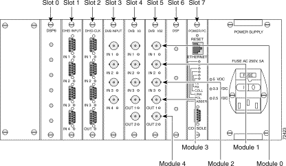
For example, a complete address of an input might be Slot 2, Module 1, which identifies the second connector from the top of the card located in the third card slot in the chassis.
 |
Note This convention, rather than the labeling on the cards, must be used to address specific slots and connectors. |
This section provides instructions for a basic configuration of the Cisco 6920. To start the configuration process, perform these steps:
Step 1 Access RateMux Manager using a web browser. The Transport Map is displayed. (See Figure 4-3.)

RateMux Manager scans for and detects all installed video input and output cards. The Transport Map feature displays the slot and module of these input/output and input cards.
Step 2 Click Chassis Configuration. The Chassis Configuration section (see Figure 4-4) displays the chassis name, IP address, Ethernet address, and version of the Cisco 6920. Verify the Cisco 6920 name and IP address.

Step 3 Scroll to the Board Type section (see Figure 4-5) and verify that all the hardware is present.

In the sample configuration shown in Figure 4-5, there are (DSP) cards in slots 0, 2, and 4, each with three DSPs. The DSPs that reside on the DSP cards are named using the following convention: Slot n, Module n starting with 0. The module number refers to the physical DSP chip on the DSP card.
A DVB I/O card occupies slot 1 with three transport feeds (input), an onboard DSP, and two output connectors. (The table shows only one output connector, which is Y configured to form two output connectors.
There are DHEI I/O cards in slots 3 and 5. Each has three transport feeds (input), an onboard DSP, and one output connector.
The DVB I/O2 card in slot 6 has three transport feeds, two onboard DSPs, and two output connectors.
The PowerPC card resides in Slot 7
Step 4 Scroll to the Software Modules section. (See Figure 4-6.)
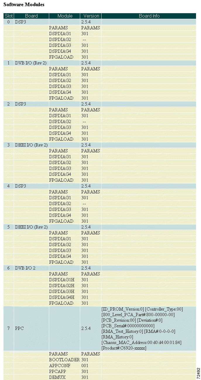
The Software Modules section provides information concerning the installed Cisco 6920 cards. The software module versions on those cards are displayed in a version table. The version table is organized by card, listing the card, followed by all the software modules on that card. Verify that the software on all boards is the same version and is current.
Step 5 In the Output Video Stream Type section, select the Output Video Stream Type (see Figure 4-7):

Digital signal processor (DSP) allocation must be performed before selecting channels.
Step 1 Access RateMux Manager using a web browser.
Step 2 Click Chassis Configuration.
Step 3 Scroll to the System DSP CPU Bandwidth Allocation section. (See Figure 4-8.)
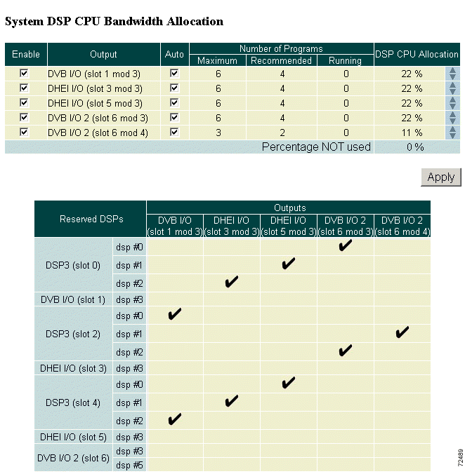
Step 4 In the DSP Allocation window (see Figure 4-9), use the Enable check boxes to designate which output ports will be used and will require DSPs.
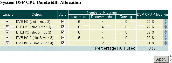
All outputs are enabled (checked) by default, and DSPs are assigned evenly among all of them.
 |
Note Outputs that have programs assigned to them cannot be disabled (unchecked). Clear the configuration before disabling them. |
Step 5 DSPs for disabled outputs become available for allocation and are moved to the "Percentage NOT used" row. Use the up arrows in the far right column to move unused DSPs to outputs. Click Apply to make the changes.
 |
Note The output DSP also is available as a demux DSP in the pool of available DSPs. |
Step 6 Check the Auto check box to automatically allocate programs to DSPs assigned to that output when a configuration is applied.
 |
Note Service is disrupted on this output when the DSP calculation is applied. |
If the Auto check box is not checked, the programs may be manually allocated to DSPs assigned to the output using the Advanced page. Service is not disrupted on this output when the DSP calculation is applied.
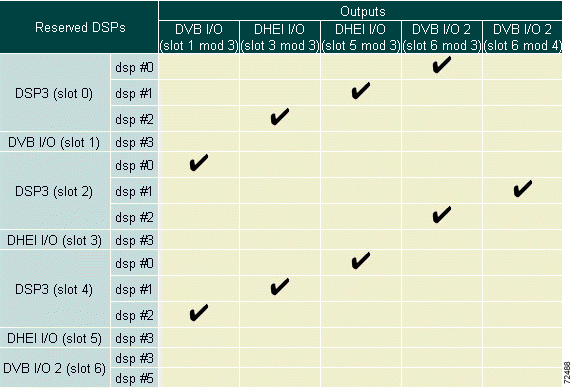
DSP-to-output assignments can be viewed on the table directly below the DSP Allocation window. (See Figure 4-10.)
Step 1 Access RateMux Manager using a web browser.
Step 2 Click Program Select Output Config to display the Output Configuration and Program Select page. See Figure 4-11.)
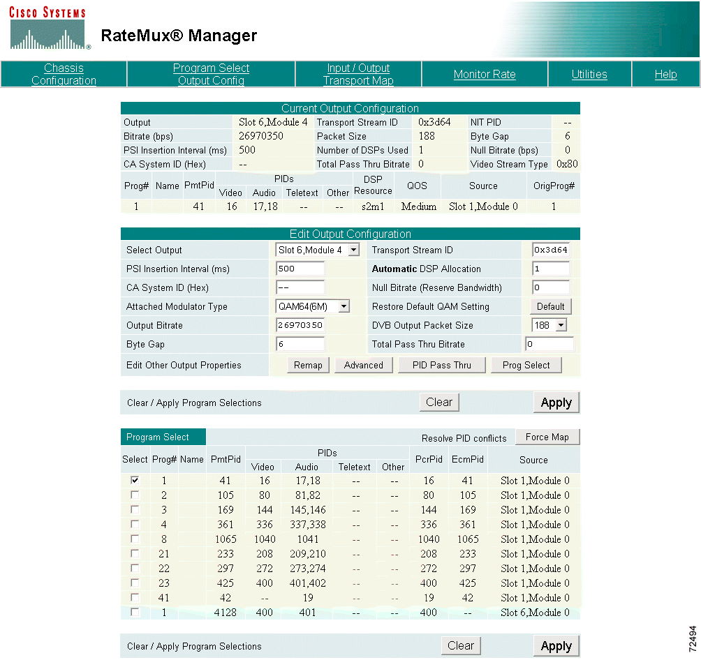
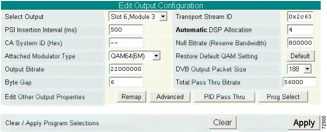
Step 3 Scroll to the Edit Output Configuration section. (See Figure 4-12.)
 |
Note The Edit Output Configuration section for DigiCable Headend Expansion Interface (DHEI) I/O and the DVB-ASI I/O cards differ. The details of each are discussed in the following substeps. |
a. The Select Output field displays the slot and connector of the output. Use the pull-down menu to select the proper card for your configuration. (See Figure 4-13.)
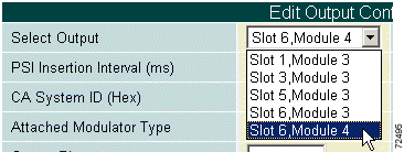
b. The Transport Stream ID field is filled in automatically. If you have specific requirements for a transport stream ID, leave this field blank or use any value that was previously automatically entered.
c. The PSI Insertion Interval field indicates the rate (in milliseconds) at which PSI data is being injected into the video stream. Enter the desired Rate.
 |
Note The recommended PSI Rate is 200. This conforms to Motorola PSI requirements. |
d. The CA System ID field displays (in hexadecimal) the Conditional Access System ID descriptor needed by the Conditional Access vendor. Change this value by entering a new value (such as
AB 34) in the field. Entering two dashes (--) indicates that the original setting should be kept. To delete the CA descriptor, enter either del or Del, then click Apply.
e. The Null Bitrate (Reserve Bandwidth) field indicates the number of NULL packets (in bits per second) being inserted into the video stream. Enter the bandwidth needed for any data insertion downstream from the Cisco 6920.
 |
Note The recommended Null rate is 300000 for systems that have Conditional Access systems on the output of the Cisco 6920. |
f. Use the Attached Modulator Type pull-down menu to choose from four quick-configuration options: QAM64(6M), QAM256(6M), QAM64(8M), or QAM256(8M). (See Figure 4-14.)

g. For each selection, the Output Bitrate and Byte Gap are automatically calculated and the values inserted into their fields.
 |
Note Analog channel bandwidth is assumed to be a default of 6 MHz. |
h. If any of the automatically calculated fields are changed after the quadrature amplitude modulation (QAM) setting is selected, click Restore Default QAM Setting to return the values to the default settings.
i. Use the DVB Output Packet Size pull-down menu to select either 188-byte mode or 204-byte mode with 16 null packets.
j. If audio-only programs (such as DMX or Music Choice) are to be passed through, calculate the peak bit rate of the sum of all these programs selected for passthrough and enter it in the Total PassThru Bitrate field.
 |
Note Music Choice recommends a PassThru Bitrate of 13,500,000 when configuring all Music programs in a single output. If the Music Choice programs (with still-frame video) are split between outputs, then use 257 kbps for each program plus 2.3 Mbps for the video stream maximum burst rate. |
a. Scroll to the Edit Output Configuration section. (See Figure 4-15).
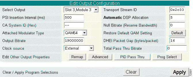
b. The Select Output field displays the slot and connector of the output. Use the pull-down menu to select the proper card for your configuration. (See Figure 4-16.)
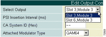
c. The Transport Stream ID field is filled in automatically. If you have specific requirements for a transport stream ID, leave this field blank or use any value that was previously automatically entered.
d. The PSI Insertion Interval field indicates the rate (in milliseconds) at which PSI data is being injected into the video stream. Enter the desired rate.
 |
Note The recommended PSI Rate is 200. This conforms to Motorola PSI requirements. |
e. The CA System ID field displays (in hexadecimal) the Conditional Access System ID descriptor needed by the Conditional Access vendor. Change this value by entering a new value (such as AB 34) in the field. Entering two dashes (--) indicates that the original setting should be kept. To delete the CA descriptor, enter either del or Del, then click Apply.
f. The Null Bitrate (Reserve Bandwidth) field indicates the number of NULL packets (in bits per second) being inserted into the video stream. Enter the bandwidth needed for any data insertion downstream from the Cisco 6920.
 |
Note The recommended Null rate is 300000 for systems that have Conditional Access systems on the output of the Cisco 6920. |
g. Use the Attached Modulator Type pull-down menu to choose either quick-configuration options: QAM64 or QAM256. (See Figure 4-17.)

 |
Note Analog channel bandwidth is assumed to be a default of 6 MHz. |
h. If any of the automatically calculated fields are changed after the quadrature amplitude modulation (QAM) setting is selected, click Restore Default QAM Setting to return the values to the default settings.
i. The Output Bitrate field allows entry of an output bit rate of a value less than the maximum bit rate supported by the DHEI interface.
j. The DHEI Packet Gap defines the number of bit clocks between MPEG packets on the DHEI output. Allowable values are 0 or 16 to 271.
k. The Clock pull-down menu allows the selection of the source of the output clock: 38.8107 MHz and 29.2657 MHz Internal or an External clock source. (See Figure 4-18.)

l. If audio-only programs (such as DMX or Music Choice) are to be passed through, calculate the peak bit rate of the sum of all these programs selected for passthrough and enter it in the Total PassThru Bitrate field.
 |
Note The Total PassThru Bitrate must be configured to support audio-only programs even if they are not configured for Program PassThru mode. The average audio-only program consumes about 300 kbps. |
 |
Note Music Choice recommends a PassThru Bitrate of 13,500,000 when configuring all Music programs in a single output. If the Music Choice programs (with still-frame video) are split between outputs, then use 257 kbps for each program plus 2.3 Mbps for the video stream maximum burst rate. |
Step 4 Click Apply to make changes or Clear to clear program selections.
 |
Note When several values are changed, it is necessary to click Apply only once to configure all values. |
Step 1 Click Prog Select in the Edit Output Configuration window. The Program Select page is displayed. (See Figure 4-19.)
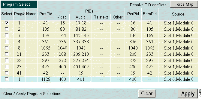
This page displays the current configuration.
Step 2 Select the programs to be included in the output.
 |
Note Click Clear to deselect all programs in the list. Clicking Clear does not restore default output parameters or original packet identifier (PID) and program numbers for each input. |
Step 3 To resolve PID conflicts, click Force Map.
Step 4 If Music Choice programs are selected, click Advanced in the Output Configuration window to display the Advanced page. (See Figure 4-20.)
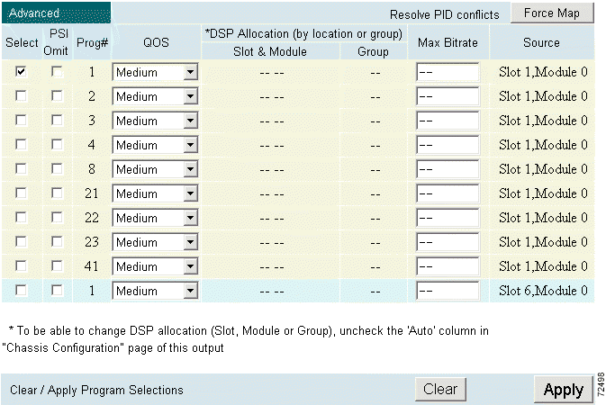
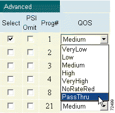
Step 5 Modify the quality of service (QoS) for each Music Choice program to pass through. (See Figure 4-21.)
Each high-definition (HD) program needs a DSP assigned to it. If any other programs are sharing the same DSP as the HD program, unexpected results can occur. Follow these steps to configure an HD program:
Step 1 Click Chassis Configuration.
Step 2 Scroll to the System DSP CPU Bandwidth Allocation window.
Step 3 Determine which output the HD program will use and be sure that Enabled is selected and Auto is not selected.
Step 4 Click Program Select Output Config and scroll to the Program Select window. Be sure that Select Output is set to the output the HD program will be on.
Step 5 Click Advanced.
Step 6 Locate the HD program. In the QOS column, use the pull-down menu and select NoRateRed (no rate reduction).
Step 7 Assign the HD program a unique group number under the Group column. (See Figure 4-22.)

Step 8 Click Apply to save the configuration.
 |
Note In Figure 4-22, the HD program is Program 1 set to NoRateRed in DSP Group 1. |
The following sections discuss configuration options not addressed in the basic configuration sections.
To configure transport inputs and outputs, click Input/Output Transport Map at the top of the RateMux Manager page to display the Transport Map. (See Figure 4-23.)

Transport streams or program names can be deleted, changed, or added:
To delete names, select the Delete option of the name to be deleted then click Apply. If the name is a program name, it is removed from the database. If a transport stream name is deleted, all program names that belong to that transport stream are deleted and the transport stream is set to its default name.
To change a transport stream or program name, edit the Name field then click Apply.
To add names, click Add Names. The Add New Names page is displayed. (See Figure 4-24.)
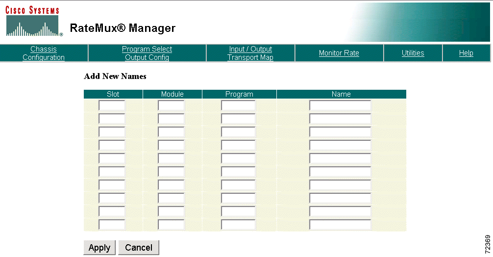
Enter the slot/module number, the program number, and the transport stream or program name, then click Apply. The name is added to the database. Click Cancel to return to the previous page.
 |
Note A maximum of ten names can be entered at a time. |
The current name database is saved in Flash memory every time the configuration of an output transport stream is changed. To list the names stored in the database, select the Display All Transponder Names option, then click Refresh. The page displays both current and previous transponder names. (See Figure 4-25.)
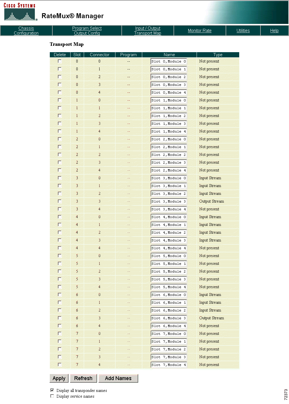
Clicking Refresh without selecting the Display All Transponder Names option (default) displays only the current names. Clicking Refresh with the Display Service Names option selected displays name entries for both transport streams and programs. (See Figure 4-26.)
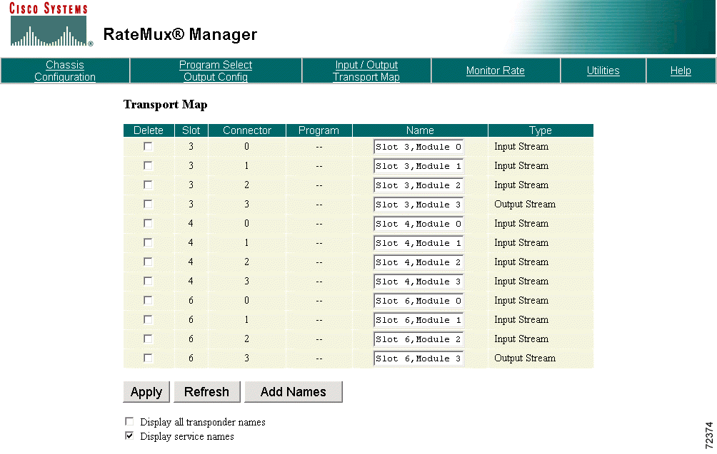
Clicking Refresh without selecting the Display Service Names option (default) displays only the transport stream names.
Data Collection Options set table information collection parameters.
Click Chassis Configuration and scroll to the Data Collection Options section. (See Figure 4-27.)

Select Disable PSI Collection to stop the collection of input PSI data and cause the Cisco 6920 to use the last collected data.
Select Disable Private Table Collection to stop the collection of private table information. When this collection is in process, in addition to collecting PAT and PMT of table ID 0x2, the Cisco 6920 starts collecting tables that are carried in the transport packets with the same PID as PMT_PID and have table IDs of 0x40, 0x41, 0xc, and 0xc1. These special tables are collected for every incoming program. The collection process usually takes 15 seconds.
If every incoming program contains all four of the special tables, the collection finishes in under 15 seconds. Otherwise, the collection times out in 15 seconds. If private table collection is enabled, wait at least 30 seconds before configuring the output transport stream. Doing so causes the Cisco 6920 to copy its latest snapshot of the PSI data (including the special tables) to the Program Select. Click Apply to commit the output transport stream configuration. This causes the snapshot of the special tables to become part of the Cisco 6920 output PSI data.
Use the SNMP Manager Addresses section to specify SNMP Manager Addresses.
Click Chassis Configuration and scroll to the SNMP Manager Addresses section. (See Figure 4-28.) Enter up to three IP addresses and click Submit.

To remove an existing SNMP manager entry, delete its address then click Submit.
 |
Note For security purposes, these addresses do not remain after resetting the system. |
The Remap function allows editing of the following fields:
 |
Note For information on PID fields, see ISO/IEC 13818-1:1994 [E]. |
To display the PID Remap page, click Program Select Output Configuration and scroll to the Edit Output Configuration section. Click Remap. (See Figure 4-29.)
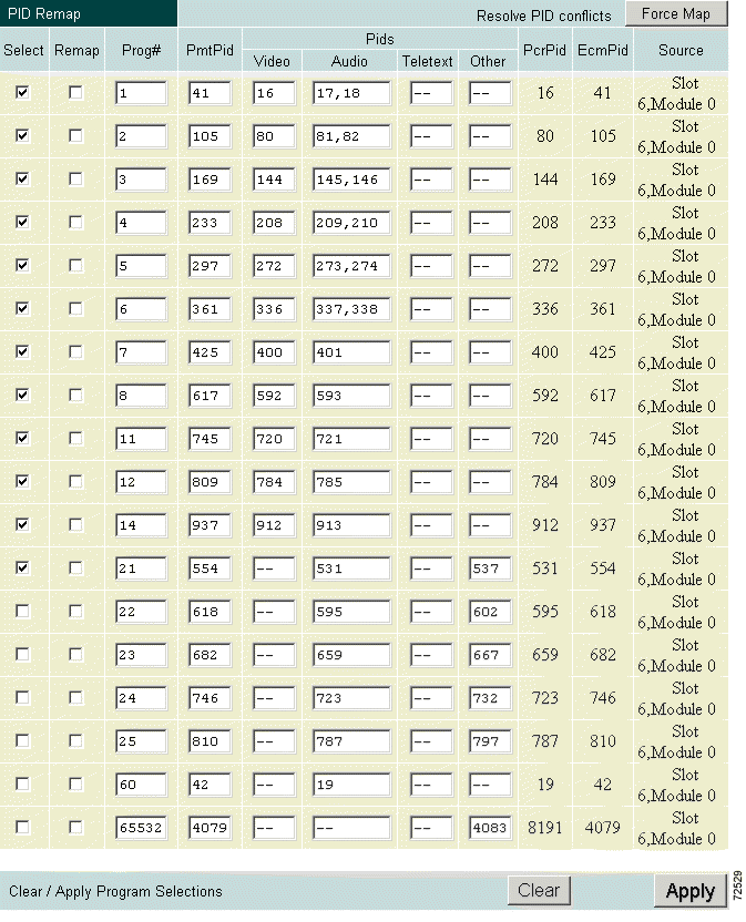
Edit the required fields. When you are satisfied with the changes, click Apply to submit the changes. If video was running, it will go blank for a few seconds while the Cisco 6920 reassigns the channel setup.
RateMux Manager assigns the transponder source and output to the channel. If you receive a warning notifying you of conflicts in channel selection, scroll down the page to check other sources and channel selections, make changes accordingly, then repeat this procedure. Another option is to click Force Map to allow RateMux Manager resolve the conflicts.
 |
Note When you use Force Map, PIDS are assigned to channels in groups of 64, starting with a base of 0. For each channel from the base, the 16th PID is assigned to video and the 17th PID to audio. The PCR follows the video PID. The PMT PID is assigned base +41. |
RateMux Manager can dynamically allocate bandwidth. By default, all channels are eligible for reassignment, with a quality of service (QoS) rate reduction value of Medium. You can also assign a QoS value to channels. These assignments rank channels in terms of eligibility for bandwidth swapping.
Click Program Select Output Configuration and scroll to the Edit Output Configuration section. Click Advanced to display the Advanced page. (See Figure 4-30.)
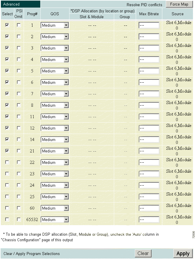
Select a channel and click the QOS pull-down menu. Choose a QoS from the menu. (See Figure 4-31.)
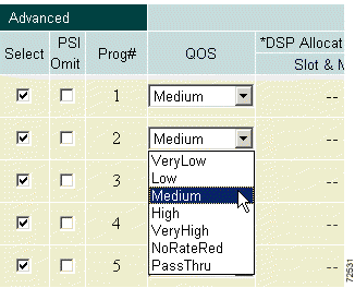
The choices are:
Optionally, click the PSI Omit check box to remove program information about this channel from the output stream. This parameter applies only if the PSI rate is not 0.
For each selected channel, change the DSP allocation by location or group.
 |
Note To change DSP allocation, be sure that the Auto column in the System DSP CPU Bandwidth Allocation section in the Chassis Configuration page is unchecked. |
Enter a maximum bit rate (in bits per second) in the Max Bitrate field to set a maximum bit rate for that particular stream. That stream's bit rate is limited to the specified value, ensuring that the bit rate at the output of the Cisco 6920 does not exceed the specified value for that stream.
Click Apply. RateMux Manager assigns the QoS selections to the selected channels and displays the results in the Current Output Configuration section. If a conflict is detected, the submitted selections are rejected. Resolve the conflicts or click Force Map to allow RateMux Manager to resolve them.
PID PassThru allows low bit rate (less than 256 kbps) CBR video streams for any channel to be passed directly from the input source to the output destination without any processing.
Click Program Select Output Configuration and scroll to the Edit Output Configuration section. Click PID Pass Thru to display the PID PassThru page. (See Figure 4-32.)
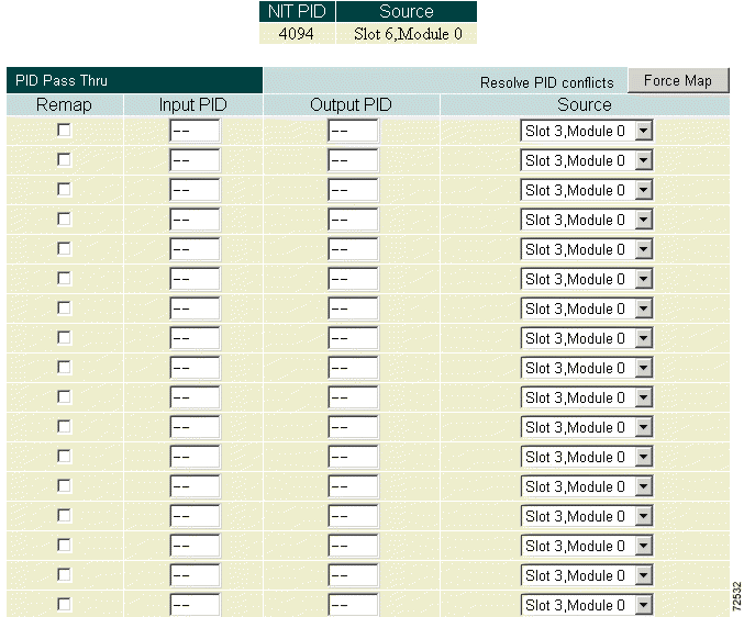
A read-only table of NIT PIDS and sources is shown right above the PID PassThru section.
To select a PassThru PID, enter the input PID, the output PID (only needed if different from the input PID), the input that PID should be extracted from, and whether the Cisco 6920 is allowed to remap the output PID to a different value in case of conflict (check Remap box).
Click Apply to save the program selections.
 |
Note If a PassThru PID is recognized as a NIT PID from the NIT PID list, the Cisco 6920 assumes that the PID should be used as the NIT PID. |
 |
Note When the output of the Cisco 6920 is connected to a transmit IRT, it must be configured to pass through a NIT PID from one of the input bit streams. This NIT PID contains time-of-day information that the IRT needs for authorization. |
The Utilities page provides three chassis reset and configuration utilities.
Click Utilities at the top of the RateMux Manager page to display the Utilities page. (See Figure 4-33.)
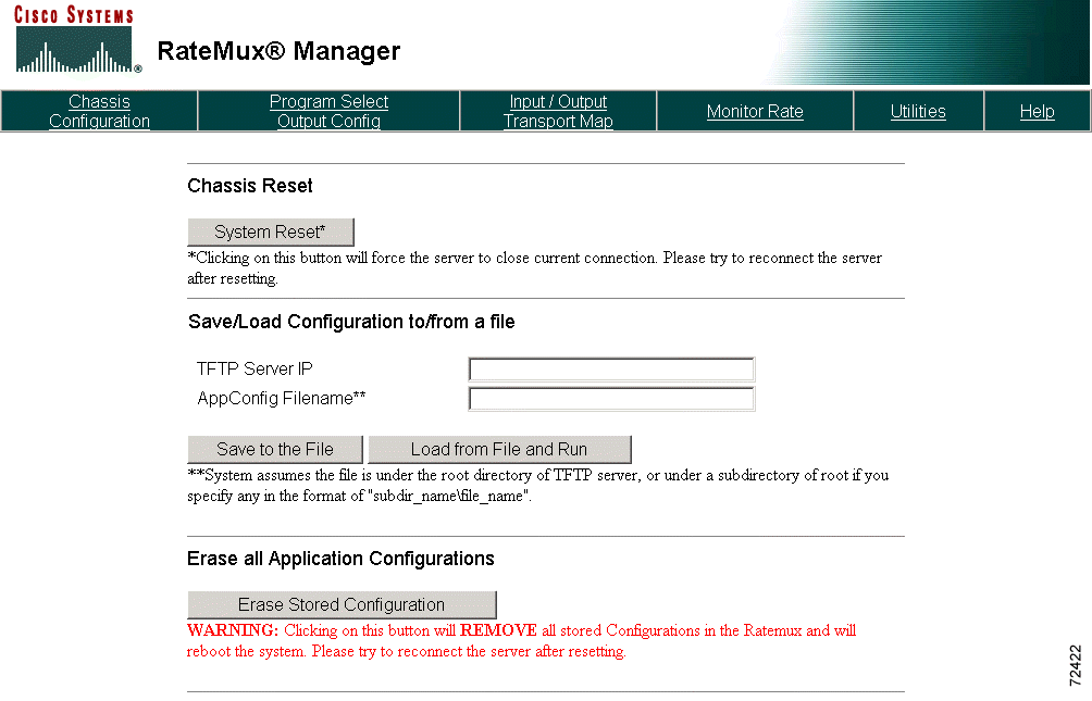
Use this utility to reset the Cisco 6920. Click System Reset (see Figure 4-34). This action activates the chassis reset circuitry equivalent to a Power Off, Power On sequence.

 |
Note System Reset causes a temporary loss of video. When System Reset is clicked, the message "System Reset will cause temporary loss of video. Are sure you want to continue?" appears, allowing you to cancel the reset, if necessary. |
 |
Note This feature is present only on PowerPC cards with the Watchdog Timer hardware |
Use this utility to upload an application configuration from the Cisco 6920 to an external TFTP server or to download a stored application configuration from the TFTP server to the Cisco 6920. Cisco recommends that you save the application configuration prior to upgrading the Cisco 6920 software.
To use this utility, enter the IP address of the TFTP server along with the application configuration file name. (See Figure 4-35.)
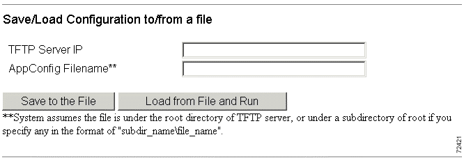
Click Save to the File or Load from File and Run.
 |
Note When using this utility, be sure that the TFTP server is operating properly. |
Use this utility to erase all stored configurations in the Cisco 6920 and reboot the system. (See Figure 4-36.)

Click Erase Stored Configuration. All stored configuration information is deleted and the Cisco 6920 is restarted.
The Help page (see Figure 4-37) provides a link to the latest user documentation for the Cisco 6920 on the Cisco web page, cisco.com.
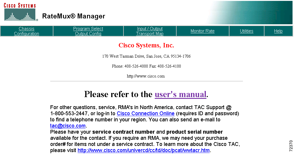
Click user's manual to access these documents which can be viewed and downloaded in either HTML or PDF format.
The Monitor Rate feature allows you to view a bar chart of input and output bit rates for each video stream selected in your channel lineup. The total input and output bit rates are also calculated and displayed. (See Figure 4-38.)
 |
Note The chart displays pre- and post-video stream bit rates and not total bit rate traffic (including data and audio). |
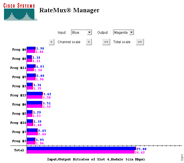
The bar chart can be customized by choosing colors for input/output bars and by changing the scale for both the individual channels and the bit-rate totals. To reduce the scale, click < to modify the scale of the individual video stream display, or click << to modify the totals display. To increase the scale, click > or >>.
![]()
![]()
![]()
![]()
![]()
![]()
![]()
![]()
Posted: Fri Sep 27 00:30:03 PDT 2002
All contents are Copyright © 1992--2002 Cisco Systems, Inc. All rights reserved.
Important Notices and Privacy Statement.