|
|

This chapter describes the site requirements for installing the Cisco 6920. The chapter contains the following sections:
Before installing the Cisco 6920, assemble the equipment needed to support your network configuration and subscriber service offering. Ensure that all power and cabling requirements are met based on the equipment to install. Also ensure that environmental conditions are met to maintain proper equipment operation.
The following guidelines will help to ensure your safety and protect the equipment. This list does not cover all potentially hazardous situations, so be alert.
 |
Warning Read the installation instructions before you connect the system to its power source. To see translations of the warnings that appear in this publication, refer to the Regulatory Compliance and Safety Information document that accompanied this device. |
 |
Warning Only trained and qualified personnel should be allowed to install, replace, or service this equipment. To see translations of the warnings that appear in this publication, refer to the Regulatory Compliance and Safety Information document that accompanied this device. |
 |
Warning Ultimate disposal of this product should be handled according to all national laws and regulations. To see translations of the warnings that appear in this publication, refer to the Regulatory Compliance and Safety Information document that accompanied this device. |
A fully configured Cisco 6920 weighs approximately 42 pounds. This chassis is not intended to be moved frequently. Before you install the Cisco 6920, ensure that your site is properly prepared so that you can avoid having to move a chassis later to accommodate power sources and network connections.
The PowerPC cards, I/O cards, input cards, and power supplies are not designed to be removed and replaced while the system is operating.
 |
Caution You must power down the system before removing or replacing any card in the Cisco 6920. |
Follow these basic guidelines when working with any electrical equipment:
 |
Caution Before opening the chassis, disconnect the video cables to avoid contact with any voltages. |
Electrostatic discharge (ESD) damage, which occurs when electronic cards or components are improperly handled, can result in complete or intermittent system failures. The PowerPC card, input/output cards, input cards, and DSP cards consist of a printed circuit board that is fixed in a metal carrier. Electromagnetic interference (EMI) shielding, connectors, and a handle are integral components of the carrier. Although the carrier helps protect the boards, use an antistatic strap whenever handling the PowerPC card, input/output cards, input cards, and DSP cards. Handle the carriers by the carrier edges only; never touch the boards or connector pins.
 |
Caution Always tighten the captive installation screws on the PowerPC card, input/output cards, input cards, and DSP cards. These screws prevent accidental removal, provide proper grounding for the system, and help ensure that the bus connectors are properly seated in the front plane. |
Following are guidelines for preventing ESD damage:
 |
Caution For safety, periodically check the resistance value of the antistatic strap. The measurement should be from 1 through 10 megohm (Mohm). |
To ensure normal operation and avoid unnecessary maintenance, plan your site configuration and prepare your site before installation. Take into account the following criteria:
The AC-input power supply uses a power factor corrector that allows the Cisco 6920 to operate on input voltage and frequency within the ranges of 100 through 240 VAC and 50/60 Hz.
 |
Note Cisco recommends installation and testing of an uninterruptible power source (UPS) with sufficient "in-rush" starting current capability to protect against power failures and power anomalies such as spikes and brown-outs at your site. A Cisco 6920 AC-input power supply has an electrical current rating of 4A, but initial starting current is higher. Size the uninterruptible power source accordingly. The UPS rating should accommodate startup in-rush currents in the event that the unit is power cycled; therefore, a 1500-watt plus rating is advisable per fully loaded Cisco 6920 chassis. The UPS also provides power buffering in the case of mains to generated power transfer. |
Table 2-1 lists the operating and nonoperating environmental site requirements. Within the specified ranges, the Cisco 6920 will continue to operate; however, a measurement approaching the minimum or maximum indicates a potential problem. You can maintain normal operation by anticipating and correcting environmental anomalies before they approach a maximum operating range.
The Cisco 6920 is cooled by convection from the bottom through the top of the chassis. Keep the top and bottom of the chassis clear of obstructions and away from the exhaust of other equipment.
| Specification | Minimum | Maximum |
|---|---|---|
Temperature, ambient operating | 32ºF (0ºC) | 104ºF (40ºC) |
Temperature, ambient nonoperating and storage | -4ºF (-20ºC) | 149ºF (65ºC) |
Humidity, ambient (noncondensing) operating | 10% | 90% |
Humidity, ambient (noncondensing) nonoperating and storage | 5% | 95% |
Altitude, operating and nonoperating | Sea level | 10,000 ft (3,050 m) |
Planning a proper location for the Cisco 6920 and the layout of your equipment rack or wiring closet are essential for successful system operation. Equipment placed too close together or inadequately ventilated can cause systems to overheat. In addition, chassis panels made inaccessible by poor equipment placement can make system maintenance difficult. Following are precautions that can help avoid problems during installation and ongoing operation.
Follow these general precautions when planning your equipment locations and connections:
Follow these precautions and recommendations when planning power connections to the Cisco 6920:
The Cisco 6920 chassis is fully assembled at the factory; no assembly is required. However, you will need the following tools and equipment to install the chassis:
In addition, you might need the following:
| Signal | Pin | Pin | Signal |
|---|---|---|---|
Transmit Data (TxD+) | 1 | 3 | Receive Data (RxD+) |
Transmit Data (TxD-) | 2 | 6 | Receive Data (RxD-) |
Receive Data (RxD+) | 3 | 1 | Transmit Data (TxD+) |
- | 4 | 4 | - |
- | 5 | 5 | - |
Receive Data (RxD-) | 6 | 2 | Transmit Data (TxD-) |
- | 7 | 7 | - |
- | 8 | 8 | - |
| Signal | Pin | Pin | Signal |
|---|---|---|---|
Transmit Data (TxD+) | 1 | 1 | Transmit Data (TxD+) |
Transmit Data (TxD-) | 2 | 2 | Transmit Data (TxD-) |
Receive Data (RxD+) | 3 | 3 | Receive Data (RxD+) |
- | 4 | 4 | - |
- | 5 | 5 | - |
Receive Data (RxD-) | 6 | 6 | Receive Data (RxD-) |
- | 7 | 7 | - |
- | 8 | 8 | - |
 |
Note A 12-foot triple-shielded Ethernet straight-through cable is included in the Cisco 6920 accessory box. This cable must be used for FCC compliance. |
The rack-mounting brackets on the Cisco 6920 are suitable for most 19-inch equipment racks. Before using a particular rack, check for obstructions (such as a power strip) that could impair rack-mount installation. If a power strip does impair a rear rack-mount installation, remove the power strip before installing the chassis in the rack, then replace it after the chassis is installed. Note that you cannot mount the Cisco 6920 on an equipment shelf, because the bottom and top of the chassis must be free from obstructions so that air can circulate through the unit.
In addition to the preceding guidelines, review the precautions for avoiding overtemperature conditions in the "Site Requirements" section. To properly install the Cisco 6920 chassis in a rack, refer to the instructions in the "General Installation" section on page 3-3.
 |
Caution To prevent the chassis from overheating, never install the Cisco 6920 in an enclosed rack or room that is not maintained within ambient operating temperatures by proper room ventilation or air conditioning. The unit will overheat if the conducted input air temperature reaches 105º F (41º C). |
This section describes considerations for setting up the cabling at your site. When planning the location of the new system, consider the distance limitations and connector compatibility as described in the following sections.
DHEI cables should not be longer than 80 inches (2 meters).
 |
Note Cisco recommends that you do not exceed specified transmission rate and distance limits. |
Belden type 8138 low capacitance computer cable:
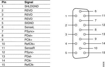
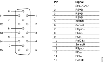
Figure 2-1 and Figure 2-2 show the signal-to-pin designations for the DHEI input and output connectors.


Cisco part number: cis72-2072-01
Cisco part number: cis72-2085-01
Cisco recommends that cables used for connecting the DVB I/O card (output only) should be "Precision Video Cable" cables or an equivalent (such as CommScope E83032 (quad-shielded) or Belden 9167 (triple-shielded) high-quality 75-Ohm coaxial cable constructed using at least 95 percent braid-over-foil shielding. This type of cable is required to ensure meeting Electromagnetic Compatibility emission requirements as well as assuring superior signal integrity.
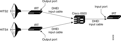
Most cable headends use integrated receiver transcoders (IRTs) from General Instrument (now part of Motorola) to receive digital programming from AT&T Headend in the Sky (HITS) and other satellite-based distributors. The IRT, which decrypts and demodulates the quadrature phase shift keying (QPSK) feed, has a DHEI (26-pin connector) output that can be interconnected with the Cisco 6920 DHEI Input or I/O module (15-pin connectors) using the CAB-6920-DHEI-Input cable. A CAB-6920-DHEI-Input cable can also be used to connect the Cisco 6920 DHEI I/O module output (15-pin connector) to the IRT DHEI input (26-pin connector) for reencryption and (quadrature amplitude modulation (QAM) of the newly stat-muxed transport stream for distribution through the cable plant. (See Figure 2-3.)

Motorola/GI has introduced a Modular Processing System (MPS), which can contain modules that decrypt, demodulate, remultiplex, reencrypt, and remodulate digital video streams. An additional DHEI or DVB-ASI module is used to interconnect the MPS to the Cisco 6920. Motorola/GI has also introduced a new DSR 4400 satellite demodulator. Both of these products use 15-pin connectors for DHEI rather than the 26-pin connectors used in the IRTs.
 |
Note Cisco does not provide the interconnect cables between the Cisco 6920 and these products. The appropriate DHEI (15-pin to 15-pin) cables are available from Motorola as an accessory. |
Many cable headends also use multiple decryption receivers (MDRs) from Scientific-Atlanta to receive digital programming from Time warner's Athena or other satellite-based distributors. The MDR, which decrypts and demodulates the QPSK feed, has a DHEI (26-pin connector) output that can be interconnected with the Cisco 6920 DHEI Input or I/O module (15-pin connectors) using the CAB-6920-DHEI-Output cable.
 |
Note It is the DHEI output cable and not the DHEI input cable (as was the case with the Motorola IRT). |
The newly stat-muxed output of the Cisco 6920 can be forwarded to a Scientific-Atlanta encryptor/modulator (for example, the D9476) via DHEI (through the 15-pin DHEI I/O output connection) with CAB-6920-DHEI-Input cable or more commonly via DVB-ASI (through the DVB-IO module). (See Figure 2-4.)

Scientific-Atlanta sells a high-density multiple QAM modulator (MQAM), that supports up to four 6-MHz QAM 256 outputs in a single rack unit. Due to the MQAM's limit of only two DVB-ASI input ports (the MQAM does not support DHEI interfaces), the Cisco 6920 cannot fully utilize the MQAM's bandwidth requirements through the existing DVB I/O card outputs.
Other headend equipment manufacturers produce equipment that typically uses only the DVB-ASI protocol. Should you encounter a satellite demodulator, MPEG encoder, or multiplexer that is to be connected to the Cisco 6920 via DHEI, keep in mind that Cisco provides cabling only for the 26-pin-to15-pin conversion. Any 15-pin-to-15-pin cabling must be acquired from the equipment vendor and not from Cisco.
![]()
![]()
![]()
![]()
![]()
![]()
![]()
![]()
Posted: Fri Sep 27 00:19:34 PDT 2002
All contents are Copyright © 1992--2002 Cisco Systems, Inc. All rights reserved.
Important Notices and Privacy Statement.