|
|

This chapter describes the procedures for rack-mounting, connecting the cables, and powering up the LightStream 1010 ATM switch at your site.
 | Caution Before installing the chassis in a rack, read the section "Safety with Electricity" in the chapter "Preparing for Installation" to familiarize yourself with the proper site and environmental conditions. Failure to read and follow these guidelines could lead to an unsuccessful installation and possible damage to the system and components. |
A rack-mount kit is included for mounting the switch in a standard 19-inch (48.7-centimeter) equipment rack with two unobstructed outer posts.
Following is the procedure for attaching the rack-mount kit and installing the switch in a wiring closet rack. Two or more people are needed to perform this procedure.
Be sure you have at least three or four feet of clearance behind the rack for maintenance. The intake and exhaust ports for cooling air are located on the front and rear and both sides of the chassis, so multiple switches can be stacked with little or no clearance in a rack. The chassis is 10.36 inches (25.9 centimeters) high.
Before rack-mounting the LightStream 1010 ATM switch, confirm that your rack-mount configuration conforms to the following criteria:
 | Caution Before you mount the switch in a rack, make sure that: the rack is secure and in no danger of falling over; the area around the rack does not exceed a maximum ambient temperature of 104ºF (40ºC); and sufficient airflow exists around the rack. |
 | Warning Two people are required to lift the chassis. Grasp the chassis underneath the lower edge and lift with both hands. To prevent injury, keep your back straight and lift with your legs, not your back. To prevent damage to the chassis and components, never attempt to lift the chassis with the handles on the power supplies or on the interface modules. These handles were not designed to support the weight of the chassis. To see translated versions of this warning, refer to the appendix "Translated Safety Warnings." |
Refer to the section "Safely Lifting the Chassis" in the chapter "Preparing for Installation."
Following are the tools and equipment needed to install the chassis:
If you are installing the chassis in a rack, you will also need the following:
Take the following steps to attach the two L brackets to the switch chassis:
Step 1 Place the chassis on the floor or on a sturdy table as close as possible to the rack, with clearance to allow you to move around the chassis.
Step 2 Use a tape measure to measure the depth of the rack. Measure from the outside of the front mounting posts to the outside of the rear mounting strip. The depth must be at least 19.25 inches (39.4 centimeters), but not greater than 32 inches (81 centimeters).
Step 3 Measure the space between the inner edges of the left front and right front mounting posts to ensure that it is 17.75 inches (45 centimeters) wide. (The chassis is 17.25 inches [43 centimeters] wide and must fit between the mounting posts.)
Step 4 Open the rack-mount kit and refer to the component checklist in Table 4-1 to verify that all parts are included.
| Quantity | Part Description | Received |
|---|---|---|
2 | L brackets (left and right) |
|
6 | M4 Phillips countersunk-head screws |
|
8 | 12-24 x 3/4-inch Phillips binder-head screws |
|
8 | 10-32 x 3/4-inch slotted binder-head screws |
|
Step 5 Depending on your installation, remove the six cover attachment screws from either the front or the rear of the switch. (See Figure 4-1.)
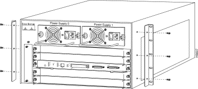
Step 6 Attach the left and right L brackets using the six M4 Phillips countersunk-head screws provided in the rack-mount kit.
Step 7 Attach the left and right cable guides, if needed, using the six M3 Phillips flat-head screws provided in the rack-mount kit. (See Figure 4-2.)
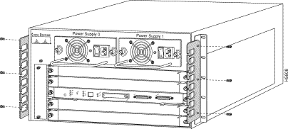
The L brackets attach the chassis to the front mounting posts. You can mount the L brackets on either the front or rear of the chassis, whichever end will be in the front of the rack.
 | Warning To prevent bodily injury when mounting or servicing this unit in a rack, you must take special precautions to ensure that the system remains stable. The following guidelines are provided to ensure your safety: |
 | Warning Two people are required to lift the chassis. Grasp the chassis underneath the lower edge and lift with both hands. To prevent injury, keep your back straight and lift with your legs, not your back. To prevent damage to the chassis and components, never attempt to lift the chassis with the handles on the power supplies or on the interface modules. These handles were not designed to support the weight of the chassis. To see translated versions of this warning, refer to the appendix "Translated Safety Warnings." |
Follow these steps to install the switch in an open rack that allows you to slide the chassis in from the front.
Step 1 Two people are required to perform this step.While referring to Figure 4-3, with a person positioned at either side of the chassis, grasp the bottom edge of the chassis with one hand near the front and the other near the back. Slowly lift the chassis in unison. Avoid sudden twists or moves to prevent injury.
Step 2 Position the chassis in the rack as follows:

Step 3 A third person should install the 10-32 x 3/4 inch slotted binder-head mounting screws through the elongated holes in the L bracket and into the threaded holes in the mounting post.
Step 4 Use your tape measure and level to ensure that the chassis is installed straight and level.
Step 5 At the front of the chassis, perform the following steps:
Step 6 Make sure that your path to the rack is unobstructed.
The rack-mount installation is now complete.
This section describes the basic network connections---Ethernet and ATM--- that you make to the switch. Using the Port Configuration Worksheet helps you to make connections and later configure each interface without having to access the rear of the chassis to check port addresses. See the section "Using the Port Configuration Worksheets" in the appendix "Configuration Worksheets."
Use the following guidelines to assist you in properly connecting the external network cables to your switch.
 | Warning A voltage mismatch can cause equipment damage and may pose a fire hazard. If the voltage indicated on the label is different from the power outlet voltage, do not connect the chassis to that receptacle. To see translated versions of this warning, refer to the appendix "Translated Safety Warnings." |
If the switch fails to operate, refer to the chapter "Confirming the Installation" to help isolate the problem, and then notify a customer service representative.
The sections that follow provide illustrations of the connections between the switch interface ports and your network(s). Interface cables and equipment, such as Ethernet transceivers and interface cables, should already be available and in place. If they are not, refer to the following section "Ethernet Connections," for descriptions of the equipment you need for each interface type to complete the connection to your network.
Most Ethernet connections do not require a transceiver on the interface cable. Figure 4-4 shows examples of typical connections. For a description of the connection equipment, refer to the section "Ethernet Connection Equipment" in the chapter "Preparing for Installation."

All Synchronous Optical Network (SONET) ATM interfaces are full-duplex. You must use the appropriate ATM interface cable to connect the ATM PAM with an external ATM network.
The ATM PAMs provide an interface to ATM switching fabrics for transmitting and receiving data at up to 622 Mbps bidirectionally.
The fiber-optic ATM PAM can support interfaces that connect to the following physical layers:
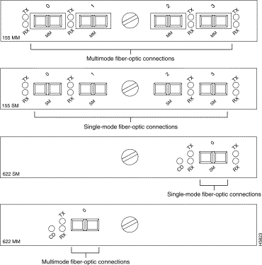
Connect the ATM interface cables as shown in Figure 4-5. For detailed descriptions of ATM cabling requirements, refer to the sections "Distance Limitations" and "ATM Synchronous Optical Networks Connections" in the chapter "Preparing for Installation."
 | Warning Class 1 laser product. To see translated versions of this warning, refer to the appendix "Translated Safety Warnings." |
 | Warning
 Do not stare into the laser beam. To see translated versions of this warning, refer to the appendix "Translated Safety Warnings."
 |
The unshielded twisted-pair (UTP) ATM interface is full duplex. You must use the appropriate ATM interface cable to connect the ATM PAM with an external ATM network.
The ATM PAMs provide an interface to ATM switching fabrics for transmitting and receiving data at up to 155 Mbps bidirectionally; the actual data rate is determined by the physical layer interface module (PLIM).
Connect the ATM interface cables as shown in Figure 4-6. For detailed descriptions of ATM cabling requirements, refer to the section "Distance Limitations" and the section "ATM Synchronous Optical Networks Connections" in the chapter "Preparing for Installation."

All coaxial ATM interfaces are full-duplex. You must use the appropriate ATM interface cable to connect the ATM PAM with an external ATM network.
The ATM PAM provides an interface to ATM switching fabrics for transmitting and receiving data at 34 and 45 Mbps bidirectionally.
The ATM PAM can support interfaces that connect to the following physical layers:
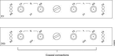
Connect the ATM interface cables as shown in Figure 4-7. For detailed descriptions of ATM cabling requirements, refer to the section"Distance Limitations" and the section "ATM Synchronous Optical Networks Connections" in the chapter "Preparing for Installation."
The ASP CONSOLE port supports a data communications equipment (DCE) EIA/TIA-232 interface type and mode. For descriptions and illustrations of each connector type, refer to the section "EIA/TIA-232 Connections" in the chapter "Preparing for Installation." For cable pinouts, refer to the section "Preparing Network Connections" in the chapter "Preparing for Installation."
When connecting a serial device, consider the cable as an extension of the switch for an external connection; therefore, use null-modem cable to connect the switch to a remote DCE device such as a modem or data service unit (DSU), and use a straight-through cable to connect the switch to a data terminal equipment (DTE) device such as a terminal or PC. (See Figure 4-8.)
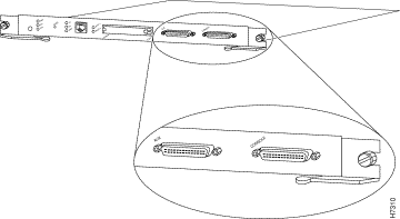
The system console port on the ASP is a DCE DB-25 receptacle for connecting a data terminal, which you will need to configure and communicate to your system. The port is located on the ASP faceplate and is labeled CONSOLE, as shown in Figure 4-8.
Before connecting the console port, check your terminal's documentation to determine the baud rate. The baud rate of the terminal must match the default baud rate (9600 baud) of the terminal you will be using. Set up the terminal as follows:
Use the proper null-modem or straight-through cable to connect a terminal or modem to the console port on the ASP; then follow the steps in the section "Starting the System."
This section describes the procedures to apply power to the LightStream 1010 ATM switch at your site. Connect an AC-input power supply, as follows:
Step 1 On one power supply, plug in the power cord.
Step 2 Connect the power-supply cord to an input line. (See Figure 4-9.)
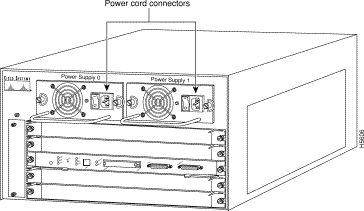
Connect the redundant power supply to a separate input line. Connect the redundant AC-input power supply as follows:
Step 1 On the redundant power supply, plug in the power cord.
Step 2 Connect the redundant power supply cord to an input line other than the initial power supply line. (See Figure 4-9.)
When all interfaces are connected, perform a final check of all connections then take the following steps to check the components and power up the system.
Step 1 Check the following components to make sure they are secure:
Step 2 Check the external power connections; the power-supply switches should still be OFF:
Step 3 Check the console terminal and make sure it is ON.
Step 4 Turn the power supply(ies) ON.
Step 5 After both power supplies are switched ON, the PS0 and PS1 LEDs on the ASP faceplate will be green.
Step 6 Listen for the system fan assembly and check the fan LED on the ASP. You should immediately hear it start operating.
Step 7 While the system initializes, the status LED on the ASP is orange until the boot is complete. Refer to the chapter "Confirming the Installation" for troubleshooting procedures.
During the boot process, the status LED on all interfaces is orange. Some LEDs may go on and remain on or go out and go on again for a short time. Some LEDs, such as the link LED, will stay on during the entire boot process. If an interface is already configured, the LEDs may go on steadily as they detect traffic on the line. Wait until the system boot is complete before attempting to verify the module LED indications.
When the system boot is complete (it takes a few seconds), the ASP begins to initialize the PAMs. During this initialization, the LEDs on each PAM behave differently (most flash on and off). The status LED on each PAM goes on when initialization has been completed, and the console screen displays a script and system banner similar to the following:
          Restricted Rights Legend
Use, duplication, or disclosure by the Government is
subject to restrictions as set forth in subparagraph
(c) of the Commercial Computer Software - Restricted
Rights clause at FAR sec. 52.227-19 and subparagraph
(c) (1) (ii) of the Rights in Technical Data and Computer
Software clause at DFARS sec. 252.227-7013.
           cisco Systems, Inc.
           170 West Tasman Drive
           San Jose, California 95134-1706
Cisco Internetwork Operating System Software
IOS (tm) IISP Software (LS1010-WI-M), Version 11.1(1.083)
Copyright (c) 1986-1996 by cisco Systems, Inc.
Compiled Wed 10-Apr-96 06:11 by
Image text-base: 0x600108C0, data-base: 0x602E8000
The first section of the script displays the banner information, including the software version.
The next portion of the script lists installed hardware configuration.
cisco ASP1 (R4600) processor with 16384K bytes of memory.
R4600 processor, Implementation 32, Revision 2.0
Last reset from power-on
1 Ethernet/IEEE 802.3 interface.
16 ATM network interfaces.
125K bytes of non-volatile configuration memory.
8192K bytes of Flash PCMCIA card at slot 0 (Sector size 128K).
8192K bytes of Flash internal SIMM (Sector size 256K).
Step 8 The following prompt will appear:
Switch>
Your installation is now complete. Refer to the chapter "Confirming the Software" or refer to the publication LightStream 1010 ATM Software Configuration Guide if additional information is needed.
|
|