|
|

Cell Relay · Technologies Compared · Benefits of ATM · ATM Label Switching · The ATM Cell · The ATM Adaptation Layer · The ATM Layer · Placing the Cells onto a Physical Transport Medium
This chapter describes the Asynchronous Transfer Mode (ATM) technology on which the LightStream 2020 enterprise ATM switch is based. If you are already familiar with ATM, you can skip this chapter.
Asynchronous Transfer Mode (ATM) is a communications standard based on cell relay techniques. The next sections discuss the cell relay and ATM technology. They also contrast ATM techniques with time division multiplexing (TDM) and other packet technologies.
Cell relay is a flexible and responsive method for multiplexing all forms of digital traffic (data, voice, image, and video). Cell relay can handle rapid changes in the quantity and pattern of the traffic in the network. All traffic is placed in fixed-length packets of information (cells) and switched at high speeds. Cell relay is generally acknowledged as the best multiplexing technology for modern communication applications because it combines the strengths of time division multiplexing (TDM) and conventional packet switching. Cell relay can process a mixture of bursty and delay-sensitive traffic simultaneously, and it can provide the quality of service that each type of traffic requires.
Also, because cell relay is based on the asynchronous transport of very short packets, it is adaptable and cost effective for a wide range of interface speeds.
ATM first appeared as the transfer mode used by Broadband Integrated Services Digital Network (B-ISDN); however, ATM is now recognized as a useful technology in and of itself. ATM is based on the specifications and standards being developed by ITU-T (formerly CCITT), ANSI, and the ATM Forum.
Each ATM cell contains a header and the data to be transferred. Cells are switched in the network based on routing information contained in the headers. ATM transports all types of traffic (data, voice, image, and video) using the same cell format.
ATM contrasts with time division multiplexing (TDM) in the way it allocates communications channels.
In TDM, communications channels are divided into fixed periods of time called frames. The frames are divided into a fixed number of equal duration time slots. Each user is assigned certain time slots within each frame. (A user can be given more than one time slot in a frame.) See Figure 1-1.

The time slots for each user occur at precisely the same time in every frame. Since the time slots are synchronous, TDM is sometimes referred to as Synchronous Transfer Mode (STM).
Users can access the communications channel only when a time slot that has been allocated to them is available. For example, user A can send messages over the communications channel only during a time slot(s) designated for user A. If there is no traffic ready to send when the slot occurs, the slot goes unused. If a user has a burst of traffic that exceeds the capacity of the designated slots, additional slots cannot be used even if they are idle. As a result, there could be a long delay in getting the burst of traffic passed over the TDM network.
In ATM, access to the communications channel is more flexible. Any user who needs the communications channel can use it whenever it is available. In contrast to TDM (Synchronous Transfer Mode), ATM imposes no regular pattern to the way users are given access to the communications channel. ATM is also described as providing bandwidth on demand.
In other packet technologies, such as HDLC, any user can gain access to the communications channel, but a user who has a long message to send can prevent other users from gaining access to the channel until the entire message has been passed. However, with ATM, every message is divided into small, fixed-length cells. No single user can retain sole access to the communication channel for a long time if other users have messages to send. See Figure 1-2.

This section describes some of the key benefits of ATM technology.
ATM standards define protocols that operate at layer 2 (the data link layer) of the International Standards Organization (ISO) seven-layer Open Systems Interconnection (OSI) model. Figure 1-3 shows the layered architecture of the OSI model.
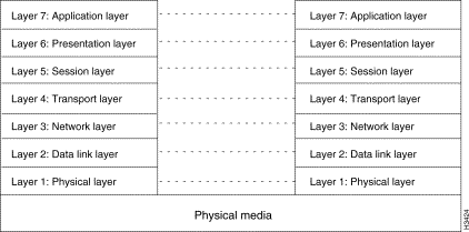
The data link layer is concerned with data transmission between two network switches. It is not concerned with transmission of an entire message between its source and destination switch—that is the responsibility of layer 3 (the network layer). Instead, the data link layer transports portions of messages (cells, in the case of ATM) between two points in the network. These points may be the source and destination of the message, or they may just be intermediate hops between the source and destination.
The data link layer may divide higher level data into smaller units (cells, in this case) whose sizes are compatible with the overall requirements of the network. Layer 2 data units contain a cell header, an information field, and some method of checking for transmission errors.
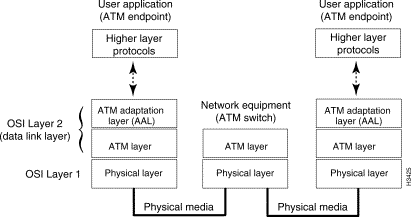
Before they can be transported across an ATM network, frames must be divided into ATM cells. The processes that divide the frames into cells occur at the data link layer (layer 2). Layer 2 is divided into two parts: the ATM adaptation layer (AAL) and the ATM layer. Once the frames are divided into ATM cells, the cells can be transferred to the physical layer (layer 1). See Figure 1-4.
ATM uses label switching, a technique in which a simple label is placed in the header of each cell. The label provides information that is used to transport the cell across the next hop in the network. Networks that do not use label switching usually require that each packet (or cell) contain the explicit address of the final destination. ATM uses label switching because it is simple and can therefore switch traffic faster than more complex techniques.
Label switching works like this:
1. A switching unit reads an incoming cell on a particular port. The incoming cell has a routing label.
2. The switching unit uses the combination of the input port on which the cell was received and the information in the label to determine where the cell should go next. It does this by referencing a routing table that correlates the incoming port and label to an outgoing port and label.
3. The switch then replaces the incoming label with a new outgoing label and sends the cell through the outgoing port, which is connected to another switching device. (The new outgoing label is taken from the routing table.)
4. This process is repeated until the cell reaches its final destination in the ATM network.
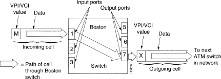
Suppose for example that your network includes a switching unit called Boston. A number of connections (data paths) go through the Boston switch. When those connections are created, a routing table is set up in the Boston switch. The table in the Boston switch has one entry for every connection that goes through the switch. The entries in the table map the incoming port and label to an outgoing port and label for each connection as shown in Table 1-1.
| Port In | Label In | Port Out | Label Out |
1 | L | 6 | Z |
1 | M | 7 | X |
2 | N | 7 | Y |
When the Boston switch receives an incoming cell on port 1 with the label M, it consults the routing table and finds that the label M should be replaced with the label X and that the cell should be passed out of the Boston switch on port 7. The cell is then transported to the switch in the network that is connected to port 7 of the Boston switch as shown in Figure 1-5.
In all cases, transporting cells using label switching requires a connection. Information about the connections is provided in the routing tables (sometimes called lookup tables) of switching and multiplexing units. ATM uses the concepts of virtual channel connections and virtual paths to accomplish this routing.
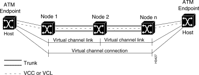
A virtual channel connection (VCC) is a series of virtual channel links (VCLs) between two ATM points. A VCL is a means of bidirectional transport of ATM cells between a point where a virtual channel identifier (VCI) value is assigned and the point where that value is either reassigned or terminated. The VCI identifies the VCL to which a cell belongs and determines where the cell should go next. Figure 1-6. shows the relationship between VCLs and VCCs in an ATM network.
VCCs are sometimes transported within virtual paths (VPs). A VP is identified by its virtual path identifier (VPI). VPs provide a convenient way of bundling traffic all heading to the same destination or traffic requiring the same Quality of Service (QoS) in the tandem network (see Figure 1-7). In a VP switching system, switching equipment checks only the VPI portion of the header to relay the traffic instead of the entire 3-byte address.

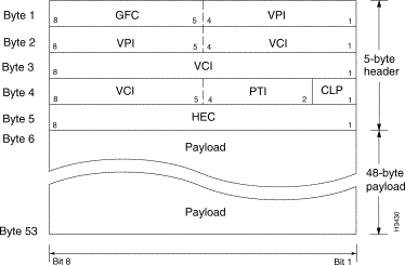
The ATM cell is the fixed-length transmission unit defined by the ATM standard. An ATM cell contains two major types of information: the payload and the header. The payload is the information to be transferred through an ATM network. It can include data, voice, image, or video. The header is the information used to route the cell through the network and ensure that the cell will be forwarded to its destination successfully.
The 5-byte header contains several different fields as described in Table 1-2.
| Header Field Name | Location in Header | Description |
First four bits of byte 1 | Controls the flow of traffic across the user-network interface (UNI) and thus into the ATM network. | |
Second four bits of byte 1 and the first four bits of byte 2 | Identifies a particular VPC. A VPC is a group of virtual connections carried between two points and may involve several ATM links. VPIs provide a way to bundle traffic that is all heading to the same destination. | |
Second four bits of byte 2, byte 3, and the first four bits of byte 4 | Identifies a particular VCC. A VCC is a connection between two active ATM entities that are communicating. It consists of a concatenation of several ATM links. | |
The fifth, sixth, and seventh bits of byte 4 | Indicates the type of information in the payload field. ATM cells carry different types of information that may require different handling by the network or terminating equipment. | |
Eighth bit of byte 4 | Indicates the cell loss priority and is set by the user. This bit indicates the eligibility of the cell for discard by the network under congested conditions. If the bit is set to 1, the cell may be discarded by the network if a congestion event occurs. | |
Byte 5 | Contains an error-correcting code calculated across the previous four bytes of the header. The HEC detects multiple bit header errors and corrects single bit errors. It provides protection against incorrect delivery of messages caused by address errors. The HEC does not provide any protection for the payload field. |
The 48 bytes following the header (the payload) contain user data.
The AAL accepts frames from higher OSI layers and adapts them to the 48-byte segments that will be placed into the payload field of ATM cells. The ATM layer accepts the 48-byte segments, adds the 5-byte header, and produces ATM cells to be transferred to the physical layer.
When ATM cells are transferred through a network, each cell is processed in isolation from all other cells. All processing decisions are made based on the cell header; no processing of the data in the payload field takes place.
The network in Figure 1-8 illustrates some examples of when and where AAL processing is performed.

Hosts A and C are connected to the network through ATM interfaces, so they do all of their AAL processing internally. The network does not do any processing for their hosts. Hosts B and D are connected to native Ethernet interfaces on Nodes A and B. Therefore Node B does all of the AAL processing for Host D. Note that Node C does not do any AAL processing at all.
Depending on the type of traffic entering the ATM network, the AAL uses one of four different AAL types to divide the traffic into small segments. These AALs are classified according to the timing relation between source and destination, constant or variable bit rate, and connection-oriented or connectionless mode. The AAL types defined in the ATM standard are listed in Table 1-3.
The AAL is divided into two sublayers: the convergence sublayer (CS) and the segmentation and reassembly sublayer (SAR) as shown in Figure 1-9.
Higher level user data is first passed to the CS of the AAL where long streams of user data (megabytes of files, for example) are divided into fixed-length packets or protocol data units (PDUs), known as CS-PDUs. Depending on the AAL you are using, the data (CS-PDUs) is divided in different ways.
The SAR portion of the AAL process accepts the larger CS-PDUs and divides them into small segments. (The SAR portion divides the CS-PDUs into 48-byte SAR-PDUs if you are using AAL5.)
If the AAL-5 SAR-PDU contains less than 48 bytes, the SAR sublayer pads it with 0s (zeros). When the AAL process is completed, the user data has been divided into 48-byte SAR-PDUs that will fit into the payload field of an ATM cell.
The ATM layer accepts the 48-byte SAR-PDUs from the SAR process, adds the 5-byte header, and produces an ATM cell for transfer to the Physical layer.
Once the data is packaged into 53-byte ATM cells, the cells are transferred to the physical layer, where they are placed onto a physical transport medium, such as fiber optic cable or coaxial cable. The process of placing cells onto the physical medium takes place in two sublayers: the physical medium dependent (PMD) and the transmission convergence (TC).
Each PMD is specific to a particular physical medium and includes definitions of proper cabling as well as bit timing. The TC sublayer generates and receives transmission frames and is responsible for all overhead associated with the transmission frame. The TC sublayer performs a convergence function by receiving a bit stream from the PMD and extracting cells.
While PMD operation depends on the physical medium, a number of TC functions remain common to all the physical layers. These include cell delineation, cell rate decoupling, HEC generation and checking, and various OAM functions. Cell delineation is the extraction of cells from the bit stream received from the PMD. Cell rate decoupling is the adaptation of the speed of the ATM Layer cell stream to the rate of the physical interface. HEC generation and checking is when the TC sublayer checks where cells start and end by calculating the HEC for every cell received. It checks this against what it expects to be the HEC of the received cell.
![]()
![]()
![]()
![]()
![]()
![]()
![]()
![]()
Posted: Wed Oct 2 06:05:15 PDT 2002
All contents are Copyright © 1992--2002 Cisco Systems, Inc. All rights reserved.
Important Notices and Privacy Statement.