|
|

What Is a LightStream Switch? · Need for a LightStream Network · LightStream Features · LightStream Product Structure
This chapter introduces the LightStream 2020 enterprise ATM switch. It describes some of the key features of the switch and its structure.
The LightStream switch is a powerful backbone ATM switch for local and wide area networks. It has premises capabilities in both ATM and fast packet switching to handle frame relay, LAN, and legacy traffic interfaces. The LightStream network creates a mission-critical enterprise backbone network that provides flexible cost-effective allocation of bandwidth, guaranteed quality of service for all applications, interoperability with past and future devices, and scalability for future applications.
Advances in computers and communications during the past 5 years have begun to overburden existing network systems and technologies. For example, today's desktop device speeds continue to grow. In the 1970s, 1.2 Kbps was considered normal speed and 9.6 Kbps was considered high speed. In the 1990s, networks using fiber technology are pushing speeds of 100 Mbps and significant speed increases are expected in the future. Also, widespread use of applications that demand large amounts of data have overburdened existing LAN/WAN technology. These applications include distributed supercomputing, high-resolution graphics (CAD/CAM, imaging, and so on), scientific visualization, network-based client/server computing, and distributed file access.
Such advances have created the need for new network architectures and infrastructures that provide higher throughput, more usable bandwidth, and a broader diversity of services. The LightStream switch was designed with these specific needs in mind.
In addition to basing the LightStream switch on ATM technology, there are a number of features that make the LightStream switch a reliable, cost-effective device that provides high-speed, broadband, open networking to many different applications.
To achieve the high throughput needed to make the LightStream switch operate effectively, most of the switching functions are performed in hardware and firmware. The hardware and firmware operate much faster than software.
The remaining tasks are implemented using distributed, concurrent mechanisms in software. Each line card includes a line card control processor that handles the more complex tasks that must be completed in 10s of milliseconds or less, such as call processing, error handling and line up/down protocol processing. Network processor software performs functions that can be completed in more than 10s of milliseconds, such as servicing network management requests.
Today's networks feature a wide variety of applications, each with its own performance requirements. One application may need a guaranteed level of service where delay variation must be minimized (for example, SNA). Another application may require service that is more cost-effective, but not guaranteed. The LightStream switch optimizes application performance by providing you with types of service that is right for each application.
Enterprise ATM switches provide cost savings by minimizing the amount of transmission bandwidth needed from carriers. The extent to which an ATM switch lowers carrier costs depends primarily on the switch's congestion avoidance strategy.
The LightStream switch has a proactive congestion avoidance feature that keeps the network from experiencing the effects of congestion by managing congestion at the edges of the network. When a LightStream network detects congestion, the sources of the congestion are identified and controlled individually based on their service guarantees. Congestion is removed at the source, link use is maximized, and mission-critical service is maintained.
The LightStream switch provides mission-critical networking, including:
The LightStream switch has a proactive congestion avoidance feature that keeps the network from experiencing the effects of congestion by managing congestion at the edge of the network. When a LightStream network detects congestion, the sources of the congestion are identified and controlled individually based on their service guarantees. Congestion is removed at the source, link is minimized, and mission-critical service is maintained.
You manage the network using a Sun SPARCstation running LightStream management software. In addition to the tools provided by LightStream, you may choose to run HP OpenView management software, from Hewlett-Packard, or another network management system that is SNMP compatible. Many management tasks can also be performed using a simple command line interface (CLI) from a terminal attached to the console port of a LightStream node.
The LightStream network uses SNMP as its management protocol and is compatible with various SNMP-based management systems. LightStream offers StreamView(TM), an SNMP-based network management system. StreamView lets you monitor, control, and configure your LightStream network. You are provided with a graphical representation of your managed objects and a mouse-driven point and click interface.
For more details on network management, see the "Network Management" chapter.
A LightStream network provides a very clear migration path to ATM. Often the introduction of a new technology forces you to replace much of your existing equipment because it is no longer compatible with the new technology. Because replacing equipment is a substantial investment, the LightStream switch is designed to let you migrate to ATM gradually.
The switch provides services that make it backward compatible with any current equipment passing constant bit rate (CBR) traffic, Ethernet, FDDI, high-level data link control (HDLC), synchronous data link control (SDLC), or frame relay frames. The LightStream switch can accept this traffic from an external device, convert it to ATM cells, and pass it through the network.
The LightStream switch can also accept ATM cells from an external device and pass those through the network. It also provides services that let it interface with equipment that supports ATM user-network (UNI), and SONET interfaces. As more ATM devices become available on the market, you can add them to your network and pass ATM traffic while still using your existing equipment.
Because of the need of greater integration, a LightStream network offers various types of service to carry traffic, such as frame forwarding, frame relay, ATM UNI, CBR, and bridging over the network.
The LightStream switch is based on industry standards allowing it to interoperate with standards-based, high-speed network devices. The LightStream switch adheres to the ATM specifications being developed by ITU-T (formerly CCITT), ANSI, and the ATM Forum. The LightStream switch also adheres to the SNMP specification, enabling it to be managed by any SNMP-compatible network management system.
The LightStream switch conforms to all of the standards listed in Table 2-1; however, not every detail of each standard has been implemented.
| Document Number | Title |
ANSI T1.403 | ATM UNI DS1 interface |
ANSI T1.618 (LAP-F) and ITU-T Q. 922 Annex A | Frame Relay (for Frame Format) |
ANSI T1.617 Annex D and ITU-T Q .933 Annex D | Frame Relay (for LMI and PVC management) |
ANSI T1.627-1993 B-ISDN | ATM Layer Functionality and Specification |
ANSI T1.606 and ITUT-T I.233 | Frame Relay (for UNI) |
ANSI X3T9.5 | FDDI Standard for I/O interfaces |
FRF.2 | Frame Relay (for NNI ) |
IEEE802.1g | Translation Bridging |
IEEE802.3 | Ethernet |
IEEE802.3 | Fiber Ethernet (for 10Base-FL) |
IEEE802.1d | Spanning Tree Protocol |
ATMF94-003397 | Circuit Emulation Service |
Internet RFC #1157 | Simple Network Management Protocol (for network management) |
Internet RFC #1213 | Management Information Base (MIB-II) |
Internet RFC #1271 | Remote Network Monitoring MIB |
Internet RFC #1248 | Ethernet Interface Type MIB |
Internet RFC #1406 | DS1/E1 Interface Type MIB |
Internet RFC #1407 | DS3/E3 Interface Type MIB |
Internet RFC #1493 | Definition of Managed Objects for Bridges |
Internet RFC #1512 | FDDI Interface Type MIB |
Internet RFC #1595 | SONET Interface Type MIB |
Compliance with standards ensures that LightStream switches can interoperate with older products and future products.
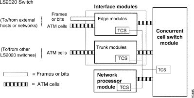
Figure 2-1 shows the key components in a LightStream switch.

The major elements in the LightStream architecture are
Together, these modules provide the functions needed to receive non-ATM frames or ATM cells from external devices and transfer ATM cells across a network.
The following sections detail each of these components.
In a LightStream switch, the concurrent cell switch module consists of a switch card plus a console/modem assembly. The switch card contains the concurrent cell switch, which interconnects all interface and NP modules. The console/modem assembly provides the physical interfaces for the console and modem ports on the switch card.
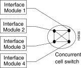
Figure 2-2 illustrates the concurrent switch architecture.

In a concurrent cell switch architecture, each interface module or NP module is interconnected with every other interface module or NP module through a concurrent cell switch that allows multiple transactions to occur between these devices simultaneously.
The use of many parallel paths allows the aggregate throughput of a LightStream switch to be extremely high, without requiring that the speed of each individual interface match the aggregate speed.
The concurrent cell switch on the switch card has 10 input ports and 10 output ports. Each output port has two channels to reduce the probability that data passing through the switch will be blocked. The total bandwidth on each port is 200 Mbps full duplex. Allowing for cell headers and switch contention (more than two switch input lines destined for the same output), this provides a sustained payload throughput of approximately 160 Mbps full duplex. All switch ports can pass traffic simultaneously resulting in a peak transfer rate of 2 Gbps and an aggregate sustained payload throughput of 1.6 Gbps full duplex.
The network processor (NP) module performs system-level tasks for the LightStream switch. It contains an NP card plus an NP access card. The NP card establishes the network connections on which traffic passes through the LightStream network. Once you establish the network connection, the interface modules recognize the traffic flows and route the traffic without further assistance from the NPs.
The NPs also do the following:
The NP access card houses an Ethernet interface for the NP module. This makes it possible for a network management station to attach to the LightStream network that has no network interface modules. Each NP module also has a disk assembly associated with it. The disk assembly contains a floppy disk drive and a hard disk drive. The floppy drive is used to load new NP and interface module software. The hard drive contains operational software, boot and configuration information, and storage for statistics.
The interface modules are divided into the following two types:
LightStream switches carry traffic received from external devices in frames, ATM cells, or a constant bit stream. If the traffic is in frames, the edge module parses incoming frames and determines the connection on which the traffic should be sent. The edge module segments the frames into ATM cells and transmits the cells across the LightStream network. It also reassembles ATM cells received from the LightStream network back into the original frames and transmits the frames from the edge interface to external devices.
If the traffic from external devices is in ATM cells, the edge module examines incoming cells and determines the connection on which the traffic should be sent, and then transmits the cells across the LightStream network; no segmentation or reassembly is needed. It also receives ATM cells from the LightStream network and transmits the cells from the edge module to external devices.
If the traffic is a constant bit stream, the edge module segments the stream into cells across the LightStream network. It also reassembles the cells back into the original bit stream and transmits the stream from the edge interface to external devices.
Edge modules contain an onboard control processor that works with the NP to set up new connections and to provide low-level information required by the network management system through the NP.
Edge modules support many different speeds and external devices. The types of edge modules are
Trunk modules connect one LightStream switch to another LightStream switch to form the LightStream backbone network. All traffic passed between trunk modules is packaged as ATM cells. The trunk module receives cells from a trunk line, recognizes the connection on which the cells arrived, and routes the cells to the next LightStream switch in the connection.
Trunk modules, like edge modules, support different speeds. The types of trunk modules are
The Test and Control System (TCS) is a fully integrated, yet autonomous, computer system located within the LightStream chassis. It is fully integrated in that there is a TCS microcomputer located on each NP, interface and switch module in a LightStream chassis. It is autonomous in that its communications path is completely separate from the LightStream switch. The TCS does not rely on the operation of any other LightStream assemblies. As long as the TCS components have power, and are themselves operational, the TCS can function.
The TCS has two primary functions:
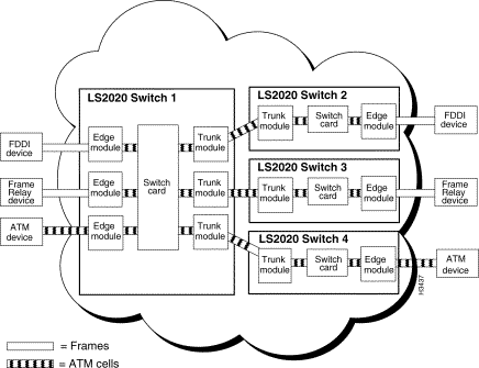
Figure 2-3 shows three LightStream switches connected in a LightStream network. As shown in the figure, external devices are connected to the LightStream switches by edge modules and traffic passing between the external devices and the edge modules is packaged as frames or ATM cells. Trunk modules connect LightStream switches to one another. Traffic passing between LightStream switches (or between any cards within a LightStream switch) is passed as ATM cells.

![]()
![]()
![]()
![]()
![]()
![]()
![]()
![]()
Posted: Wed Oct 2 06:04:08 PDT 2002
All contents are Copyright © 1992--2002 Cisco Systems, Inc. All rights reserved.
Important Notices and Privacy Statement.