|
|

Before configuring a LightStream switch, you must understand the physical and functional components of a LightStream switch that have configuration attributes. This section briefly reviews those components and discusses how they relate to configuration. For more detailed information, refer to the LightStream 2020 System Overview.
This chapter begins with a very brief description of a LightStream network, which is provided as background. It then discusses configurable objects in the order that you will encounter them as you configure a LightStream node. For instance, it describes chassis and line cards first because you must configure these objects before you can configure ports on the line card. It then describes configuration items (such as PVCs and bridging) that can only be defined after ports have been configured.
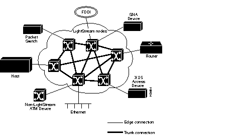
A LightStream network contains LightStream switches that are connected to one another by trunk connections. Edge connections link LightStream nodes to devices outside the LightStream network backbone. (See Figure 2-1.)
To support these connections, the LightStream switch provides
This section describes only the physical components of a LightStream switch that have configurable attributes. For a description of all switch components see the LightStream 2020 System Overview.
Each LightStream chassis contains one active network processor (NP), a set of interface modules (a interface module consists of a line card with an appropriate access card, and one active switch card that connects the line cards together and to the NP. (Backup NP and switch cards may also be present.) A logical block diagram of these components is shown in Figure 2-2. Each component is described in one of the following sections.
The chassis is the basic configurable unit. Attributes associated with the chassis include chassis ID number, name, physical location, and line cards.
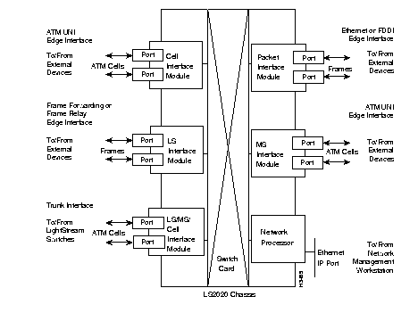
The NP is the principal computational and storage device in a LightStream node. Each node has at least one NP and at most two. In a system with two NPs, one is primary (active) and the second is secondary (backup). The secondary NP automatically becomes active if the primary NP fails. One NP occupies slot 1, and the other, if present, occupies slot 2 in the LightStream chassis. Each NP is connected to a floppy disk drive (for loading software such as LightStream application programs) and to a hard disk (for storage of the applications, configuration, and other data).
Configuration attributes associated with an NP are IP addresses and SNMP agent attributes.
Line cards provide data transfer functions. lightStream currently offers the following line cards:
With the exception of the PLC, the line cards can operate as either an edge or a trunk card. Edge cards perform the functions needed to transfer data to and from external devices. Trunk cards perform the functions needed to transfer data between LightStream switches. The PLC only operates as an edge card.
Settings in the switch's local configuration database, which are read at power-up, determine if a line card operates as either a trunk or an edge. The settings determine the firmware and software to be used; the hardware is the same in either case.
The active logic for the physical layer interface for each port (line drivers/receivers, etc.) is provided by access cards. Each line card, therefore, is associated with an access card that determines the physical layer interface supported for its ports, such as OC-3c, T3, or RS-449. Some line cards support more than one type of access card. In the configurator, line cards and their associated access cards are considered as a single unit.
Configurable attributes at the card level are name and type. After specifying these attributes, the configurator then allows you to specify ports for the line card and their attributes; these are called port-level attributes.
The following subsections describe the available line cards in more detail.
An LSC can be configured to operate as either an edge or a trunk card. The following subsections describe the functions of edge and trunk interfaces in a network, capabilities provided by the LSC, types of information that must be configured, and the protocols and physical layer interfaces supported by the LSC.
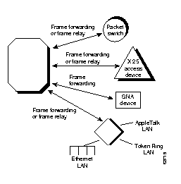
Through its associated access cards, an LSC edge interface provides up to eight external ports to devices outside the LightStream network. An LSC edge card can provide any combination of frame relay and frame forwarding interfaces.
If a port is active, you can configure it for information such as the type of port (frame forwarding or frame relay), network interface type (DCE or DTE), bit rates, maximum frame size, and PVC endpoints. Frame relay interfaces have additional attributes that include LMI type.
Figure 2-3 shows some edge connections that can be supported by the LSC.
An LSC configured as a trunk card provides a maximum of eight ports for connections between LightStream switches. Each trunk port connects to another trunk port on a LightStream LSC and is a termination point for a link within the LightStream network. The LSC trunk ports operate at rates from 56 Kbps to 3.584 Mbps, including T1 or E1 rates.
If a port is active, you can configure it for information such as the bit rate and network interface type (DCE or DTE).
An MSC can be configured to operate as either an edge or a trunk card. The following subsections describe the capabilities provided by the MSC, types of information that must be configured, and the protocols and physical layer interfaces supported by the MSC.
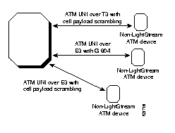
Through its associated access cards, an MSC edge interface supports up to two external ports to devices outside the LightStream network. These ports provide two ATM user-network interfaces (UNI) operating over T3 or E3 lines.
If a port is active, you can configure it for information such as the type of port (E3 or T3), cell payload scrambling, and PVC attributes.
Figure 2-4 shows some edge connections supported by an MSC.
The MSC access cards each provide a maximum of two ports for connections between LightStream switches. Each trunk port connects to another trunk port on a LightStream MSC card and is a termination point for a link within the LightStream network. The MSC trunk ports can run over T3 or E3 leased lines provided by a common carrier.
If a port is active, you can configure it for information such as the type of card (T3-trunk or E3-trunk), cell payload scrambling (enabled or disabled), and for t3 only, DS3 line type (clear channel or C-bit parity).
A CLC can be configured to operate as either an edge or a trunk card. The following subsections describe the capabilities provided by the CLC, types of information that must be configured, and the protocols and physical layer interfaces supported by the CLC.
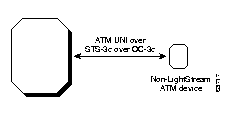
Through its associated access card, a CLC edge interface supports up to two external ports to devices outside the LightStream network. These ports provide two STS-3c interfaces operating over OC-3c lines.
If a port is active, you can configure i for information such as cell payload scrambling (enabled/disabled), clocking type (internal/external), and PVC attributes.
Figure 2-5 shows the edge connection that can be supported by a CLC card.
The CLC access card provides one port for connection between LightStream switches. The trunk port connects to another trunk port on a LightStream CLC and is a termination point for a link within the LightStream network. The CLC trunk port provides an OC-3c interface.
If a port is active, you can configure it for information such as cell payload scrambling (enabled/disabled) and clocking type (internal/external).
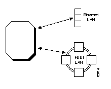
Unlike the other line cards, a PLC can only be configured to operate as an edge. The following subsections describe the capabilities provided by the PLC, types of information that must be configured, and the protocols and physical layer interfaces supported by the PLC.
Through its associated access cards, a PLC edge interface supports external ports to connect to either an FDDI LAN or an Ethernet LAN. The FDDI access card provides two dual-attach (DAS) ports. The Ethernet access card provides 8 ports; six of the ports are 10BaseT and two ports can operate as either 10BaseT or AUI.
Configuration attributes for an FDDI port include notify timer, link error rate cutoff, and link error rate alarm.
Configurable attributes for an Ethernet port include status and name.
Figure 2-6 shows the edge connections that can be supported by a PLC.
.
The LightStream switch supports LAN bridging for the FDDI and Ethernet ports. The LAN switching capabilities include MAC address learning, translation between different media, fragmentation (for IP packets only), custom filtering, and the spanning tree protocol.
Access cards provide the physical layer interface that connects to other devices. Although LightStream ports are physically located on access cards, the configurator associates each port with its line card rather than its access card. Like the line cards, the access card hardware is the same whether the port is configured as an edge or trunk. Table 2-1 shows LightStream line cards and the physical layer and higher level protocols that they support.
| Line Card | Physical Layer Interface | Trunk or Edge | Higher Level Protocol at Edge |
|---|---|---|---|
| LSC | RS-4491
V.351 X.21 | T or E
T or E T or E | FF, FR
FF, FR FF, FR |
| MSC | T3
E3 | T or E
T or E | ATM UNI
ATM UNI |
| CLC | STS-3c with OC-3c | T or E | ATM UNI |
| PLC | FDDI
Ethernet | E
E | LAN bridging
LAN bridging |
Virtual channel connections (VCCs) connect source and destination hosts across a LightStream network. Each VCC is associated with a software-selected route through the LightStream network based on the service requirements of the VCC. All traffic associated with that VCC follows the same route. See the LightStream 2020 System Overview for more information on VCCs.
A frame relay or ATM UNI source host may be connected to multiple destination hosts or may have multiple connections with the same destination host. Similarly, an FDDI or Ethernet attach may have multiple connections to one or more LAN hosts. However, a frame forwarding host can have only one connection to another device. The frame forwarding service provides a virtual wire between the two end systems. In any case, each of these connections has a separate VCC in both directions: from Node A to Node B and from Node B to Node A.
The LightStream 2020 establishes VCCs in either of two ways: by provisioning and implicit set-up. These methods are described in the following subsections.
You must provision for VCCs for the following line cards, when configured as edge connections:
Provisioning requires that you define the endpoints of VCCs by configuring them manually through the configurator. All VCCs set up in this way are Permanent Virtual Circuits (PVCs). They are considered permanent because
You can provision for a PVC before the network is brought online or while the network is operating. When you provision for a PVC, you specify the ports where it begins and ends. You also set a number of VCC attributes: VCIs (virtual channel identifiers) or DLCIs (data link connection identifiers--used for frame relay circuits only); and bandwidth allocation attributes such as insured and maximum data rates. The configurator allows you to configure PVC attributes for both ends of the PVC at the same time.
The PLC uses implicit VCC set-up. Implicit set-up occurs when the PLC determines that a VCC, with the desired characteristics, doesn't exist between the two endpoints. When this happens, the PLC works with the NP to establish a VCC to the destination and then routes the data across it. Although you don't provision for VCCs, you still need to configure the PLC and its port-level attributes.
The VCCs that are set-up implicitly aren't considered permanent because
The LightStream switch operates as a fully compliant IEEE 802.1d-1990 bridge. The LightStream switch supports translation and transparent bridging for Ethernet-to-FDDI, Ethernet-to-Ethernet and FDDI-to-FDDI. The PLC and associated access cards provide the hardware and software needed to interface to FDDI and Ethernet LANs. Refer to the LightStream 2020 System Overview for a detailed description of the LightStream switch's bridging capabilities.
Once you have configured the ports on PLC cards, you can then configure or change spanning tree bridge attributes, custom filters on bridge ports, and static routes for bridge ports.
Virtual LAN internetworking (VLI) allows you to separate network management, administration, performance and scalability from the physical aspects of the network. Through VLI, the LightStream switch allows you to partition network devices according to the problem you are trying to solve. See the LightStream 2020 System Overview for more information on VLI concepts.
Release 2.0 supports VLI workgroups. The main purpose for creating the workgroups is to provide access control. Organizations frequently require administrative subdivision of its members into distinct communities of interest (workgroups), with restricted access between them. This provides privacy between the communities and limits the effect of organization-specific activity of one community on another.
Attributes associated with workgroups include workgroup name, workgroup ID, and ports associated with a workgroup.
|
|