|
|

The LightStream 2020 multiservice ATM switch (LS2020 switch) traffic management facility, called ControlStream, allows network administrators to maximize available network resources. ControlStream provides the capability to control network resource allocation and ensure efficient use of resources that have not been explicitly allocated.
This chapter is recommended reading if you plan to perform the following tasks:
The ControlStream traffic management facility controls two key aspects of the quality of service (QoS) provided to every virtual channel connection (VCC) in an LS2020 network:
The first section of this chapter discusses transmit priority. Delay-sensitive traffic can be given preferential treatment in an LS2020 network by assigning it a higher transmit priority.
The remainder of this chapter discusses support for allocating network bandwidth, which is controlled by four complementary mechanisms that operate at different levels in the network, as indicated below:
These bandwidth allocation mechanisms are supported by two additional traffic management facilities:
When more than one cell or packet is waiting to be forwarded through a switch, trunk, or edge port, cells or packets on VCCs with a higher transmit priority are always forwarded before cells or packets on VCCs with a lower priority. Consequently, traffic on a higher priority VCC experiences consistently less delay than traffic on a lower priority VCC traversing the same path.
Transmit priority levels in an LS2020 network are defined as follows:
The fourth and fifth priority levels ensure that the network remains responsive under all traffic conditions.
For details on setting the transmit priority attributes, see the LightStream 2020 Configuration Guide.
To efficiently use network resources, an LS2020 network keeps track of the bandwidth available at each trunk and edge port. Two categories of bandwidth are defined for purposes of allocating transmission capacity in an LS2020 network:
You use allocated bandwidth for traffic that must be passed through the network under all circumstances. This bandwidth is explicitly reserved for use along the path of a VCC.
Figure 4-1 shows the relationship between allocated and best effort bandwidth on a trunk or edge port.

The allocated bandwidth is the total amount of bandwidth currently reserved by VCCs passing through the port. Allocated bandwidth rises and falls as VCCs are added, removed, or modified.
Best effort bandwidth is the sum of the following:
The availability of unallocated bandwidth is tracked by the global information distribution (GID) service described in the chapter entitled "ATM Technology." Availability of best effort bandwidth is tracked by the rate-based congestion-avoidance system, which is discussed later in this chapter.
The connection admission control (CAC) mechanism determines whether the network can support a requested VCC by establishing a potential path between the two endpoints for the VCC and deciding whether enough bandwidth exists along that path to support the new VCC.
When a new VCC is created, its bandwidth requirements are determined by configuration parameters set by the network administrator. The CAC mechanism uses two of these parameters:
The network rejects a VCC if no path exists with the capacity to accept the full insured traffic rate. However, the network permits a VCC to be established through the use of trunk or edge ports that do not have the capacity to accept the full maximum rate.
The LS2020 network reserves 100 percent of the insured rate for each connection it accepts. As a result, insured traffic is never dropped under conditions of network congestion. The network reserves only a fraction of the difference between the maximum rate and the insured rate, thereby ensuring that consumers of best effort bandwidth are distributed evenly across available trunks.
When a VCC is removed from the network, the bandwidth reserved for the VCC becomes available for reallocation.
Traffic policing refers to network mechanisms used to detect, discard, or modify ATM cells that violate the quality of service (QoS) parameters agreed to during connection setup. Although applicable to both public and private networks, traffic policing is most often done by public ATM service providers who base their tariff practices on a guaranteed QoS contract.
In an LS2020 network, traffic policing is accomplished at the edges of the network for both frame-based and cell-based traffic. The traffic policing mechanism decides whether to accept a unit of incoming traffic (packet or cell), and whether that traffic is to be carried using allocated or best effort bandwidth.
Every VCC in an LS2020 network is controlled by a traffic policer at the input edge port. The operation of the policer is governed by the insured and maximum rates discussed in the previous section, plus two additional parameters:
The relationships among the VCC traffic policing parameters are illustrated in Figure 4-2.

The total rate is the aggregate bandwidth that the LS2020 network is currently accepting for a given VCC. This rate varies over time depending on information received from the rate-based congestion-avoidance system. The total rate is never lower than the insured rate, nor is it ever higher than the maximum rate. The excess rate is the difference between the total rate and the insured rate.
The operation of the traffic policer is also influenced by two parameters not shown in Figure 4-2:
These parameters are per-VCC configuration elements set by the network administrator. They determine how much traffic can be buffered instantaneously for an individual VCC.
As traffic arrives for transmission on a VCC, the LS2020 network uses the total rate and maximum burst parameters to determine which traffic, if any, should be dropped before it enters the network.
The insured rate and insured burst parameters are used to distinguish between insured traffic (using allocated bandwidth) and best effort traffic (using best effort bandwidth). Best effort traffic can be dropped within the network under conditions of traffic congestion.
LS2020 traffic policers use the leaky bucket algorithm required by the ATM Forum UNI specification.
The leaky bucket algorithm uses two parameters to control traffic flow:
The leaky bucket algorithm also uses two state variables:
The leaky bucket algorithm operates on each incoming cell, as indicated in the following formula:
virtual time = max (virtual time, current time)
if (virtual time + 1/average rate > current time + burst)
drop the incoming cell
else
put the cell in the bucket
virtual time = virtual time + 1/average rate
If, for example, the average rate is 10 cells per second, and the burst is 50 cells, the virtual time and current time remain the same as long as the input rate remains at or below 10 cells per second.
If an instantaneous burst of 25 cells is received, the virtual time moves ahead of the current time by 2.5 seconds. If this is followed immediately by a second burst of 30 cells, the virtual time moves ahead of the current time by 5 seconds, and the last 5 of the 30 cells are dropped.
For packet traffic, the unit of incoming data is larger than a single ATM cell. For packet interfaces, the leaky bucket algorithm takes the packet size into account, as shown in the following formula:
virtual time = max (virtual time, current time)
if (virtual time + (packet size / average rate) >   current time + burst)
drop the incoming packet
else
segment the packet into cells
put the cells in the bucket
virtual time = virtual time + (packet size/average rate)
In this version of the algorithm, packet size is the number of cells required to transport the packet across the network, including the cell overhead imposed by the processing that occurs in the ATM adaptation layer (AAL).
The algorithm drops the entire packet if it does not fit into the volume available in the leaky bucket. Therefore, it is important to make sure that the burst size on a packet interface is large enough to accommodate at least one or two maximum-size packets.
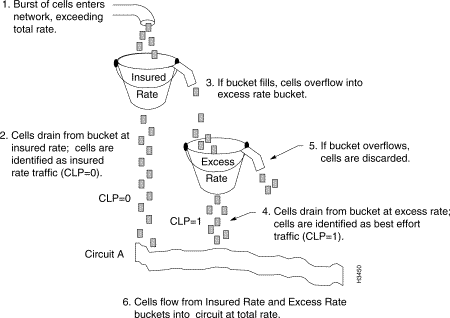
The relationships of the leaky buckets in an LS2020 traffic policer are shown in Figure 4-3.

The insured rate bucket in Figure 4-3 determines whether an incoming unit of data (packet or cell) can be accommodated by the insured bandwidth for the VCC. The applicable parameters for this leaky bucket are the insured rate and the insured burst for the VCC. If the test succeeds, the unit of data is segmented into cells (if it is a packet) and prepared for transmission by the LS2020 switch.
The excess rate bucket determines whether enough best effort bandwidth is available to accommodate the incoming unit of data. The applicable parameters for this leaky bucket are the excess rate and maximum burst for the VCC. If the test succeeds, the unit of data is segmented into cells (if it is a packet) and prepared for transmission by the LS2020 switch.
All traffic entering the network through the excess rate bucket is tagged by having its cell loss priority (CLP) bit in the cell header set to "1." This allows the selective cell discard mechanism to distinguish between traffic using best effort bandwidth and traffic using allocated bandwidth.
The following examples illustrate how the LS2020 traffic policers operate in typical network situations.
For the most part, traffic policers admit only as much traffic as the network can accommodate. Occasionally, simultaneous traffic surges by several different sources overload trunk or output ports to the point that cells must be discarded. In such cases, cells are selected for discard according to the cell drop eligibility level assigned to them at the edge of the network.
A cell can be assigned one of three levels of drop eligibility:
These cell drop eligibility levels are described in Table 4-1.
Because insured cells use allocated bandwidth, they are never selected for discard when traffic congestion occurs. Best effort and best effort plus cells consume unused bandwidth and, therefore, can be dropped under conditions of network congestion. These two levels of cell drop eligibility are assigned on a per-VCC basis by setting a configuration parameter.
| Type of Service | Drop Eligibility | Cell Action |
Most eligible to be dropped | Dropped first when network congestion occurs. | |
Less eligible to be dropped | Dropped next after attempt at best effort transmission when network congestion occurs | |
Insured (also known as guaranteed) | Least eligible to be dropped | Never dropped when network congestion occurs |
The LS2020 rate-based congestion-avoidance mechanism monitors resource utilization within the network and periodically updates traffic policers to admit only as much best effort traffic as the network can accommodate.
This mechanism provides real-time control for preventing congestion and reacting to congestion when it occurs. Network congestion occurs when the traffic load exceeds the capacity of a network transmission resource. Congestion results in increased traffic delays and reduced network throughput.
Because the LS2020 network does not permit over-allocation of insured bandwidth, insured traffic is not affected by traffic congestion. Therefore, the LS2020 rate-based congestion-avoidance mechanism regulates only best effort and best effort plus traffic.
Congestion occurs primarily because resource allocation for best effort traffic relies on the statistical nature of such traffic. Since traffic sources are not likely to generate bursts at the same time, networks are generally designed to have less bandwidth capacity than the aggregate input/output capacity of attached hosts. This characteristic contributes to the economic advantage that a network has over a collection of comparatively costly, dedicated lines.
When short traffic bursts occur that exceed the capacity of the network, the selective cell discard mechanism drops best effort traffic. However, this solution works only for short-lived congestion situations. If traffic continues to exceed the capacity of the network, it is more efficient to drop traffic at the edge of the network, since doing so allows more bandwidth to be used by traffic that will reach its destination.
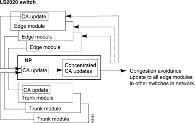
The rate-based congestion-avoidance mechanism operates as a continuous loop (see Figure 4-4). Trunk and edge modules periodically generate congestion-avoidance updates and pass the updates to associated NPs. Each NP then concentrates this information into a larger update and sends it out to every edge module in the network.

Figure 4-5 shows the effect that the rate-based congestion-avoidance mechanism has on traffic policers for a VCC carrying both best effort and insured traffic.

The important characteristics of a rate-based congestion-avoidance mechanism include the following:
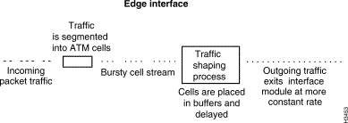
Traffic shaping minimizes the occurrence of traffic bursts on the network. You can shape traffic by segmenting it, placing it into buffers, and delaying its propagation into the network. These actions ensure a more constant flow of network traffic.
In an LS2020 network, traffic shaping is performed at all packet interfaces (see the incoming packet traffic in Figure 4-6). Traffic entering ATM UNI interfaces, however, does not need to be shaped, since such traffic obeys the traffic policing parameters established for each VCC.

![]()
![]()
![]()
![]()
![]()
![]()
![]()
![]()
Posted: Wed Oct 2 06:02:47 PDT 2002
All contents are Copyright © 1992--2002 Cisco Systems, Inc. All rights reserved.
Important Notices and Privacy Statement.