|
|

This chapter describes the Asynchronous Transfer Mode (ATM) technology on which the LightStream 2020 multiservice ATM switch (LS2020 switch) is based.
You should read this chapter if you need a general understanding of ATM technology in relation to other networking technologies in widespread use today. To this end, this chapter contrasts the relative strengths and weaknesses of existing data communications and telecommunications technologies with the attributes unique to the new, emerging ATM cell relay technology.
In particular, this chapter focuses on how ATM devices efficiently process and transmit user traffic as discrete, fixed-length ATM cells at very high speeds.
ATM technology can be used in the following types of networking environments:
ATM technology is rapidly being implemented in these networking environments to enable the seamless interconnection of local area networks (LANs) and wide area networks (WANs). Furthermore, ATM technology enables the switching and transport of multiple traffic types at comparatively high speeds in a single switching fabric.
In general, the LS2020 is the product of a standards-based implementation and development process. As a technical leadership product, however, the LS2020 ATM internal routing mechanisms were developed in advance of official industry standards and implementation agreements.
For this reason, the mechanisms that provide a path for setting up ATM virtual channel connections (VCCs) in an LS2020 network are Cisco proprietary and should be so regarded (see the section entitled "LS2020 ATM Internal Routing Mechanisms" later in this chapter).
Similarly, the LS2020 in its current implementation, does not support switched virtual connections (SVCs) by means of the ATM Forum UNI 3.0/3.1 signaling protocol. Nevertheless, an understanding of SVCs as an important ATM connection type is helpful to an overall understanding of ATM technology. Hence, SVCs are discussed in the following section and mentioned wherever appropriate throughout this chapter.
ATM technology supports the following types of communications services:
Frame Relay, SMDS, and CRS are "fastpacket" transmission technologies that are playing a prominent role in communications of the 1990's. A generic ATM platform can support all three of these fastpacket technologies, as well as CE services.
A network that supports cell relay services is based on user data units called cells. Such cells are formatted according to a standard layout and sent sequentially in a connection-oriented manner (by means of an established communications path) to remote destinations in the network.
Cell relay services are being used for emerging multimedia and video conferencing applications that require both high transmission capacities and a guaranteed quality of service (QoS). For such applications, cell relay technology provides the most efficient means for transporting data expediently and reliably through the network.
Hence, cell relay services are generally regarded as the best data multiplexing technology available for today's current and emerging communications needs. ATM combines its unique strengths with those inherent in existing data communications and telecommunications applications.
Typically, cell relay services support two types of network connections:
ATM has evolved to its current state of prominence through the collaborative efforts of the following standards bodies:
The power and flexibility of ATM derive from two primary attributes:
Consequently, ATM affords the following benefits to network users:
The following sections contrast ATM cell relay technology with other data communications and telecommunications technologies of historical significance. Also discussed are the underlying principles, concepts, and implementation techniques on which ATM cell relay technology is based.
Three major communications technologies are in use in industry and commerce today:
This section contrasts the uses, characteristics, and relative benefits of these communications technologies.
Data communications typically involve Ethernet, Token Ring, FDDI, Frame Relay, and X.25 data transmission services, all of which employ variable-length packets for data transfer. For these services, variable-length packets make more efficient use of communications channels than is the case with the time-division multiplexing (TDM) techniques commonly used in telecommunications applications (see next section).
Each of these data communications technologies addresses specific networking needs. For example, FDDI offers high transmission speeds, but typically requires users to pay a premium for 100 Mbps, fiber-based network access. Frame Relay, a protocol designed expressly for transferring LAN traffic, takes advantage of today's high quality, fiber-based networks to deliver data in a virtually error-free manner. X.25, a well-established communications protocol, is inherently slower than either Frame Relay or ATM and typically employs noisy, trouble-prone analog circuits for data transport.
All these packet switching technologies employ connectionless protocols that typically generate traffic at irregular or "bursty" intervals. In a connectionless service, no predetermined path or link is established over which information is transferred. Rather, the packets themselves contain sufficient addressing information to reach their destinations without establishing prior connections between the data senders and receivers. This connectionless service is also sometimes referred to as "packet transfer mode" (PTM).
Telecommunications technologies typically use dedicated physical lines, circuit switching techniques, and small, fixed-size frames to carry voice traffic. This connection-oriented, circuit switching technology generates traffic of uniform length at regular, time-sensitive intervals. Hence, TDM techniques are typically used for handling voice traffic.
TDM uses communications channels that are segmented into fixed periods of time called frames. Frames are further divided into a fixed number of time slots of equal duration (see Figure 1-1). Each user is assigned one or more time slots within each frame for exclusive use. For example, Figure 1-1 shows that User A is allocated two time slots per frame.

The time slots allocated for each user occur at precisely the same time in every frame. Since the time slots are synchronous, TDM is sometimes referred to as synchronous transfer mode (STM).
A user can access the TDM communications channel only when time slots allocated to it are available. If no user traffic is ready to send when the designated time slot occurs, that time slot is simply unused.
Similarly, a user sending a burst of traffic that exceeds the capacity of the designated time slots in any given frame cannot use additional slots, even if such slots are idle. Consequently, a delay will occur before the remaining user traffic can be transferred.
The continuing shift in emphasis from older data processing techniques to faster digital switching techniques, combined with the increasing availability of high bandwidth fiber optic cable, have brought dramatic changes in the nature of telecommunications networks. These advances have brought about the following changes:
However, as important as these advances are, they do not provide the most efficient solutions to today's communications needs. For example, carrying nonvoice data over telecommunications networks is very inefficient, requiring telecommunications users to acquire more dedicated bandwidth capacity for their voice applications than they typically use on a regular basis.
Thus, increasing bandwidth and adding special facilities to relieve network bottlenecks create expensive idle capacity during periods of low network utilization. Moreover, such changes may quickly become obsolete in the face of periodic organizational realignments that significantly alter the patterns of communication within the enterprise.
The solutions to these kinds of problems are found in ATM cell relay technology.
ATM is a connection-oriented data transmission technology in which user information traverses the network through a pre-established path or link between two ATM network endpoints. A network endpoint is that locus in an ATM network where an ATM connection is either initiated or terminated.
ATM switches incorporate self-routing techniques for all ATM cell relay functions in the network. This means that each ATM cell finds its way through the network switching fabric "on the fly" using routing information carried in the cell header.
In other words, an ATM switch accepts a cell from the transmission medium, performs a validity check on the data in the cell header, reads the address in the header, and forwards the cell accordingly to the next link in the network. The switch immediately accepts another cell—one that may be part of an entirely unrelated message—and repeats the process.
The cell header provides control information to the ATM layer of the ATM architecture (see Figure 1-3). The ATM layer, in combination with the physical layer, provides essential services for communications throughout an ATM network.
Since ATM protocols are not tied to any particular transmission rate or physical medium, a communications application can operate at a rate appropriate to the physical layer technology used for data transport. Furthermore, because ATM cell transmission is asynchronous in nature, delay-tolerant traffic (such as user data) can be freely intermixed with time-sensitive traffic (such as voice or video data).
Figure 1-2 illustrates the asynchronous nature of user traffic in an ATM network. Note that there is no predictable or discernible pattern in the way users are allocated cells in the ATM communications channel for data transmission.

The fixed-size format of ATM cells enables the cells to be switched (routed) through the network by means of high-speed hardware without incurring the overhead ordinarily associated with software or firmware in traditional packet-switching devices.
In ATM communications, access to the communications channel is much more flexible than with TDM communications. Any ATM user needing a communications channel can gain access to that channel whenever it is available. Also, ATM imposes no regular pattern on the way users are granted access to the channel. Thuys, ATM provides transmission bandwidth to users on demand.
In the packet-handling technologies discussed earlier, any user can gain access to the communications channel, but a user sending a long message can prevent other users from gaining access to the channel until the entire message is sent. However, with ATM, every message is segmented into small, fixed-length cells that can be transported through the network as needed. Thus, no single user can monopolize the ATM communications channel to the exclusion of other users with pending message traffic.
ATM technology offers the following primary benefits:
ATM affords the following user benefits:
From a network point of view, two main types of broadband services are supported by ATM cell relay technology:
These types of services are described in Table 1-1.
ATM standards define protocols that operate at the layer 2 level (the data link layer) of the International Standards Organization (ISO) 7-layer Open Systems Interconnection (OSI) reference model. These standards define processes that occur in the ATM adaptation layer (AAL) and the ATM layer of the ATM protocol reference model (see Figure 1-3).
The AAL performs two fundamental, and complementary, tasks:
The ATM layer is that part of the ATM protocol that operates in conjunction with the physical layer to relay cells from one ATM connection in the network to another.
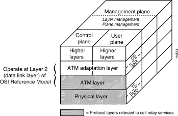
The ATM protocol reference model is patterned after the OSI reference model. However, the former differs from the latter in that it consists of three planes: the control plane, the user plane, and the management plane. The functions of these planes, which operate across all four layers of the ATM architecture, are summarized briefly below:
The interactions within and between the four layers comprising the ATM architecture in accomplishing ATM communications are summarized briefly below. Referring to Figure 1-3 will be helpful as you read this material.
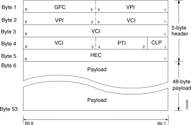
An ATM cell is a fixed-length, standard unit of data transmission for all cell relay services in an ATM network (see Figure 1-4). The first five bytes of the ATM cell serve as the cell header. The cell header contains information essential to routing the cell through the network and ensuring that the cell reaches its destination.

This 5-byte header is divided into fields that contain identification, control, priority, and cell routing information (see Figure 1-5). The remaining 48 bytes constitute the cell payload—the informational substance of the ATM cell. ATM cells are transmitted serially through the network, beginning with bit 8 in the first byte of the cell header.
Arranging data into fixed-length cells makes effective use of high-speed transmission media (such as T3, E3, and OC3 trunks), because fixed-length cells can be processed by hardware at electronic speeds while incurring a minimum of software overhead. Hence, transit delays for cells flowing through an ATM network are reduced or eliminated altogether.
An overriding advantage of handling data as fixed-length cells is that this format enables the network to accommodate not only rapid changes in the quantity of network traffic, but also in the pattern of that traffic. Consequently, an ATM network can simultaneously handle a mixture of bursty traffic and delay-sensitive traffic, while at the same time providing services essential to other traffic types.
The structure of an ATM cell is the same everywhere in the network, with the exception of a small (but important) variation in the cell header that differentiates an ATM UNI cell header from an ATM NNI cell header.
Specifically, part of the VPI field in the ATM UNI header (bits 5 through 8 of byte 1 in Figure 1-5) is reserved as a generic flow control (GFC) field, while the ATM NNI header provides for a larger range of VPI values (through bits 5 through 8 of byte 2, in addition to bits 1 through 4 of byte 1). This larger range of VPI values that can be defined in an ATM NNI cell header reflects the greater use of virtual paths (VPs) in the network for trunking purposes between ATM inter-switch and ATM inter-network interfaces.
All traffic to or from an ATM network is prefaced with a virtual path identifier (VPI) and a virtual channel identifier (VCI). A VPI/VCI pair identifies a single virtual circuit (VC) in an ATM network. Each VC constitutes a private connection to another node in an ATM network and is treated as a point-to-point mechanism for supporting bidirectional traffic. Thus, each VC is considered to be a separate and complete link to a destination node.
Table 1-2 describes the fields of the ATM UNI/NNI cell header in detail.
| Header Field Name | Location in Header | Description |
|---|---|---|
Last four bits of Byte 1 | The GFC field is used when passing ATM traffic through a user-to-network (UNI) interface to alleviate short-term overload conditions. A network-to-network (NNI) interface does not use this field for GFC purposes; rather, an NNI uses this field to define a larger VPI value for trunking purposes. | |
First four bits of Byte 1 and last four bits of Byte 2 | Identifies virtual paths (VPs). In an idle or null cell, the VPI field is set to all zeros. (A cell containing no information in the payload field is either "idle" or "null"). A virtual path connection (VPC) is a group of virtual connections between two points in the network. Each virtual connection may involve several ATM links. VPIs provide a way to bundle ATM traffic being sent to the same destination. | |
First four bits of Byte 2, all of Byte 3, and last four bits of Byte 4 | Identifies a particular virtual channel connection (VCC). In an idle or null cell (one containing no payload information), the VCI field is set to all zeros. Other non-zero values in this field are reserved for special purposes. For example, the values VPI=0 and VCI=5 are used exclusively for ATM signaling purposes when requesting an ATM connection. A VCC is a connection between two communicating ATM entities; the connection may consist of a concatenation of many ATM links. | |
Second, third, and fourth bits of Byte 4 | This 3-bit descriptor identifies the type of payload the cell contains: either user data or special network management cells for performing certain network operation, administration, and maintenance (OAM) functions in the network. ATM cells can carry different types of information that may require different handling by the network or the user's terminating equipment. | |
First bit of Byte 4 | This 1-bit descriptor in the ATM cell header is set by the AAL to indicate the relative importance of a cell. This bit is set to 1 to indicate that a cell can be discarded, if necessary, such as when an ATM switch is experiencing traffic congestion. If a cell should not be discarded, such as when supporting a specified or guaranteed quality of service (QoS), this bit is set to 0. This bit may also be set by the ATM layer if an ATM connection exceeds the QoS parameters established during connection setup. | |
Byte 5 | The HEC field is an 8-bit cyclic redundancy check (CRC) computed on all fields in an ATM UNI/NNI cell header. The HEC is capable of detecting all single-bit errors and certain multiple-bit errors. This field provides protection against incorrect message delivery caused by addressing errors. However, it provides no error protection for the ATM cell payload proper. The physical layer uses this field for cell delineation functions during data transport. | |
1. For a network-to-node (NNI) interface, the GFC field serves as part of the VPI field for trunking purposes. | ||
The processes that map user information (data, voice, and video) into an ATM format, and vice versa, occur at Layer 2, the data link layer, of the OSI reference model. For ATM purposes, Layer 2 consists of the following elements:
Figure 1-6 illustrates the relationship of these ATM elements to the physical layer.
Once user data is mapped into ATM cells in Layer 2, the cells are conveyed to Layer 1, the physical layer, for transport through the network to destinations by means of physical media and ATM switches.
An ATM endpoint, as illustrated in Figure 1-6, can be either the point of origin (the source) of an ATM cell or the destination of a cell. Hence, each ATM endpoint represents one end of a connection between communicating peers in the network.
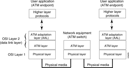
Subsequent sections describe the types of traffic handled by ATM networks and the specific attributes that distinguish one traffic type from another. Finally, the functions and interactions of the active ATM elements depicted in Figure 1-6 are described in detail.
During the early development phase of Broadband Integrated Services Digital Network (BISDN) technology, several traffic classes were defined that permit networks to carry multiple traffic types for high-bandwidth applications such as data, voice, and video.
The following traffic classes for BISDN networks are supportable by ATM:
The ATM adaptation layers associated with the four traffic classes listed above provide required services to the higher layer protocols and user applications. Five different, service-specific AAL categories have been defined (specifically, AAL1 through AAL5) to handle one or more of the four BISDN traffic classes supportable by ATM networks.
The operation of each AAL varies according to the type of traffic that the AAL is optimized to handle. In other words, each traffic class imposes certain data processing and handling requirements on the AAL.
However, there is no stipulation in ATM standards that prevents an AAL designed to service one traffic class from being used to service another class. For example, it is common for AAL5 to handle Class B traffic and for AAL1 to handle Class C traffic.
Traffic classes are categorized according to the following attributes:
Given these traffic attributes, the ITU-T has categorized network traffic classes and AAL types as outlined in Table 1-3.
Although Table 1-3 describes all four traffic classes, discussions in later sections focus particularly on ATM traffic processing in AAL1 and AAL5, since these two AALs are most pertinent to ATM technology as presently implemented for the LS2020 switch.
The AAL can be regarded as the single most important element of the ATM architecture. It is the AAL that provides the versatility to handle different types of traffic, ranging from the continuous voice traffic generated by video conferencing applications to the highly bursty messages typically generated by LANs—and to do so with the same data format, namely the ATM cell.
Note, however, that the AAL is not a network process. Rather, AAL functions are performed by the user's network terminating equipment on the user side of the UNI. Consequently, the AAL frees the network from concerns about different traffic types.
How AAL processes are carried out depends on the type of traffic to be transmitted. Different types of AALs handle different types of traffic, but all traffic is ultimately packaged by the AAL into 48-byte segments for placement into ATM cell payloads.
Consequently, several different AALs have been defined for services such as data transport, voice propagation, video conferencing, etc., as described in Table 1-3. The AAL is concerned with the end-to-end processes used by the communicating peers in the network to insert and remove data from the ATM layer.
The ATM layer is designed to make ATM networks more reliable, flexible, and user-friendly than other types of networks; it is the AAL that provides the ability to support many different traffic types and user applications. Also, the AAL isolates higher layer protocols and user applications from the intricacies of ATM.
The AAL performs two main functions in service-specific sublayers of the AAL (see Figure 1-3):
The purpose of these two sublayers is to convert user data into 48-byte cell payloads while maintaining the integrity and identity of user data. These AAL sublayers are described briefly below:
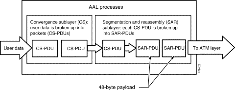


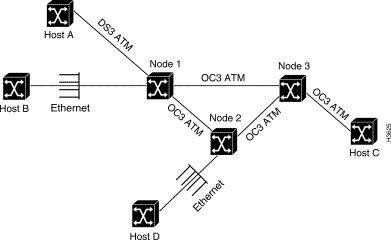
Figure 1-10 shows an example of ATM network topology and the instances in which AAL data processing is or is not performed by a particular node in the network.
In contrast, hosts B and D are connected to native Ethernet interfaces on nodes 1 and 2, respectively. Therefore, node 1 performs all AAL processing functions for host B; similarly, node 2 performs all AAL processing functions for host D. However, given the network topology shown, Node 3 is not required to perform any AAL processing functions whatever.
In this type of service, misordering of cells is considered more problematical than losing cells. Hence, a 3-bit sequence number (SN) is added when forming the basic unit of information transfer (the SAR-PDU) for AAL1 processing (see Figure 1-11). The sequence number embodied therein assists in detecting and correcting lost or misinserted cells.
In AAL1 traffic processing, user data is transferred between communicating peers at a constant bit rate after an appropriate connection has been established. AAL1 traffic services include the following:
The functions of the CS sublayer depend on the particular AAL1 traffic services required and may involve some combination of the following:
In processing AAL1 data at the source, the SAR sublayer receives the 3-bit sequence number (SN) from the CS that has been inserted into the segmentation and reassembly protocol data unit (SAR-PDU) header (see Figure 1-11). At the receiving end of the connection, the SN is passed to the communicating peer CS to detect the loss or misinsertion of cell payloads during transmission.
Also, the SAR sublayer accepts a 47-byte block of data from the CS and adds a 1-byte SAR-PDU header to form a 48-byte payload. At the destination end of the connection, the peer SAR sublayer accepts the 48-byte payload from the ATM layer, strips off the 1-byte SAR-PDU header, and passes the remaining 47 bytes of data to the CS.
Figure 1-11 shows the data format for processing AAL1 traffic.
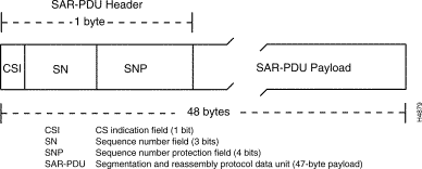
The SAR sublayer also has the optional capability to indicate the existence of the CS sublayer. The SAR receives this indication through a 1-bit field called the CS indicator (CSI) carried in the SAR-PDU header (see Figure 1-11). This CSI field is conveyed to the peer CS at the other end of the virtual connection.
Both the SN and CSI fields are protected against bit errors through a 4-bit sequence number protection (SNP) field also carried in the SAR-PDU header. This field enables both single-bit and multiple-bit error detection to be performed. If the SN and the CSI fields are corrupted and cannot be corrected, the peer CS is so informed.
AAL5 has been designed to process traffic typical of today's LANs. Originally, AAL3/4 was designed to process this kind of traffic. However, the inefficiency of AAL3/4 for handling LAN traffic led to the use of AAL5 for such traffic.
AAL5 provides a streamlined data transport service that functions with less overhead and affords better error detection and correction capabilities than AAL3/4. AAL5 is typically associated with variable bit rate (VBR) traffic and the emerging available bit rate (ABR) traffic type.
Another AAL5 attribute contributing to its efficiency is the use of the payload type indicator (PTI) field in the ATM cell header (see Figure 1-5) to indicate that the cell is supporting AAL5 traffic, rather than using space in the cell payload to so indicate. Also, AAL5 calculates a 32-bit cyclic redundancy check (CRC) over the entire AAL5 protocol data unit in order to detect cell loss and the misordering or misinsertion of cells.
For purposes of AAL5 traffic processing, the CS is divided into two parts:
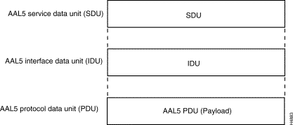 Transport Service
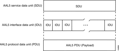
The basic unit of information transfer for AAL5 processing is the common part convergence sublayer protocol data unit (CPCS-PDU). AAL5 enables the transport of variable-length CPCS-PDUs that contain from 1 to 65,535 bytes between communicating peers in an ATM network. The format of these variable-length frames is shown in Figure 1-14.
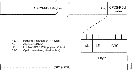
If needed, the CPCS-PDU payload is padded to align the resulting frame with an integral number of ATM cells. The padding field is used strictly for filler purposes and does not convey any useful information.
During AAL5 processing, the CPCS-PDU trailer is appended to the payload to perform the following functions:
The ATM layer performs two primary functions:
The ATM layer performs cell multiplexing, cell header generation and removal, and VPI/VCI translation. Although ATM layer operations are relatively uniform across the network, such operations depend on whether the ATM layer is inside an ATM endpoint or inside an ATM switch. In other words, the ATM layer operates differently in network endpoints and ATM switches.
For example, the ATM layer must generate and remove ATM cell headers in a network endstation (a source or destination endpoint). In a network switching device, however, the ATM layer must simultaneously multiplex/demultiplex ATM cells belonging to several different connections. Additionally, it must translate the VPI/VCI values in the header of each received cell to determine where each cell should be sent next (that is, it must determine the next transmission link in the network). In so doing, it communicates with the peer ATM layer of other switching devices through the VPI/VCI mechanisms provided in each cell's 5-byte header.
In an ATM source endpoint, the ATM layer exchanges a cell stream with the physical layer, inserting idle cells if no higher layer information is waiting to be transmitted, or inserting empty cells if such cells are needed to comply with established quality of service (QoS) parameters. Upon receiving cells from the physical layer, the 48-byte cell payload is passed to the AAL, along with other parameters, such as the payload type indicator (PTI) value or the cell loss priority (CLP) value (see Figure 1-5).
Upon receipt of an ATM cell at a port of an ATM switch, the ATM layer determines from the cell's VPI/VCI values the port to which the cell should be relayed and changes the VPI/VCI values accordingly to this new (outgoing) port. The ATM layer then forwards the cell to the new port, changes the VPI/VCI values to indicate the next link in the transmission path, and then passes the cell down to the physical layer of the outgoing port for transmission to that link.
The ATM layer may also set a bit in the PTI field if traffic congestion is experienced; it may also change the CLP field when enforcing appropriate traffic shaping and policing algorithms, such as the leaky bucket algorithm described in the chapter entitled "Traffic Management" and illustrated in Figure 4-3.
In an ATM switch, the ATM layer also ensures that cells from the same virtual connection are not misordered and that system requirements, such as maximum end-to-end latencies, are met. The ATM layer must also provide adequate buffering and congestion control mechanisms for ATM traffic.
Figure 1-15 illustrates the processes performed by the ATM layer for outbound ATM cells. The ATM layer accepts the 48-byte SAR-PDUs from the segmentation and reassembly (SAR) sublayer of the AAL, builds a 5-byte header for each SAR-PDU, and produces 53-byte ATM cells for delivery to the physical layer for transport to an ATM destination endpoint.

After user data is conveyed to the physical layer from the ATM layer, the next step is to place the cells onto a physical transport medium, such as fiber optic cable (for long distance transmission) or coaxial cable (for local transmission). The processes that accomplish this important function occur in two sublayers of the physical layer: the transmission convergence (TC) sublayer, and the physical medium dependent (PMD) sublayer. These sublayers are described in the section below entitled "Physical Layer Elements."
For transport of ATM cells through a network, the cells require an interface to one of the existing physical layers defined in current ATM networking protocols. Accordingly, the physical layer provides the ATM layer with access to the network's physical data transmission medium, and the physical layer proper transports ATM cells between peer entities in the network that support the same transmission medium.
However, since ATM technology does not necessarily depend on any particular physical medium for data transport, ATM networks can be designed and built using a variety of physical device interfaces and media types, the most prominent of which is the fiber-based transmission medium defined by the Synchronous Optical Network (SONET) standard.
The SONET data rate and framing standards are designated as Synchronous Transport Signal (STS-n) levels; the related SONET optical signal standards are designated as Optical Carrier (OC-n) levels.
For the STS level, "n" represents the level at which the respective data rate is exactly "n" times the first level. For example, STS-1 has a defined data rate of 51.84 Mbps; therefore, STS-3 is three times the data rate of STS-1, or 3 x 51.84 = 155.52 Mbps. Similarly, STS-12 is 12 x 51.84 = 622.08 Mbps, and so on.
Corresponding to each data rate and framing standard is an equivalent optical fiber standard. For example, the OC-1 fiber standard corresponds to STS-1, OC-3 corresponds to STS-3, and so on. The OC-n standard defines such items as fiber types and optical power levels.
Higher data rates in an ATM network can be achieved in a number of ways. STS-12, for example, can be implemented as 12 multiplexed STS-1 circuits, as four multiplexed STS-3 circuits, or as one single STS-12 circuit. If the STS level is being implemented as a single circuit, it is called a concatenated (or clear) channel connection and is so indicated with a "c" appended to the level designator (as in STS-3c, OC-3c, or STS-12c).
Carrying ATM cells as SONET frames enables both LAN and WAN networks to use the same data rates and framing standards, thereby ensuring easier integration of and internetworking between geographically disparate LAN and WAN domains which, historically, have been implemented with different transmission rates.
LANs typically interconnect workstations, peripherals, terminals, and other devices in a single building or a relatively small geographic locale. LAN standards specify the cabling and signaling requirements at the physical and data link layer of the OSI reference model, embracing such communications technologies as FDDI, Ethernet, and Token Ring.
Due to the layered architecture of the BISDN protocol stack, ATM is totally media independent. Many physical layer types can be implemented to serve a variety of data rate and physical interconnection requirements. Table 1-4 shows the specifications for the asynchronous digital hierachy of physical interfaces, while Table 1-5 shows the specifications for the SONET STS-n Synchronous Transport Signal hierarchy.
| Signal Type | Bit Rate | Description |
|---|---|---|
DS0 | 64 Kbps | One voice channel |
DS1 | 1.544 Mbps | 24 DS0s |
DS1C1 | 3.152 Mbps | 2 DS1s |
DS2 | 6.312 Mbps | 4 DS1s |
DS3 | 44.736 Mbps | 28 DS1s |
1The "C" in DS1C does not imply concatenation, as does the "c" in STS-3c. | ||
| Signal Type | Bit Rate | Description |
|---|---|---|
STS-1/OC-1 | 51.84 Mbps | 28 DS1s or one DS3 |
STS-3/OC-3 | 155.52 Mbps | 3 STS-1s byte interlaced |
STS-3c/OC-3c | 155.52 Mbps | Concatenated, indivisible payload |
STS-12/OC-12 | 622.08 Mbps | 12 STS-1s, 4 STS-3cs, or any mixture |
STS-12c/OC-12c | 622.08 Mbps | Concatenated, indivisible payload |
STS-48/OC-48 | 2488.32Mbps | 48 STS-1s, 16 STS-3cs, or any mixture |
Interfacing ATM traffic to a wide range of physical transmission media occurs by means of two function-specific sublayers in the physical layer: the transmission convergence (TC) sublayer, and the physical medium-dependent (PMD) sublayer (see Figure 1-3). The functions of these two sublayers are described briefly below.
Internal routing is a mechanism that provides a path for setting up ATM virtual channel connections (VCCs) in an LS2020 network. Routing is an essential function in setting up any of the following types of connections in an LS2020 network:
The LS2020 internal routing architecture is shown in Figure 1-16. The major elements of this architecture are described in the following sections.
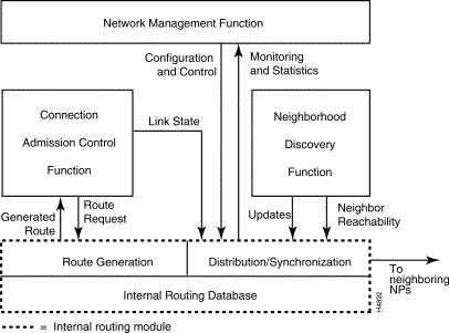
The functions that provide a route for ATM VCCs in an LS2020 network are described briefly below:
These three elements of the internal routing module are described in separate sections below.
To enable PVCs and SVCs to be set up between any two endpoints in an LS2020 network, an internal routing database must first be established in all the LS2020 switches in the network.
This database is established primarily at network configuration time by downloading configuration information to each LS2020 switch in the network. The database is then kept up to date by an internal routing module (see Figure 1-16) as LS2020 switches are added to or deleted from the network, or as the cards in the LS2020 chassis are changed, or as individual port assignments are changed.
Software processes in the internal routing module are invoked at frequent intervals to update the routing database with state information describing every link in the network.
The routing database is replicated in the network processor (NP) of every LS2020 switch in the network. Also, the database is synchronized with all other switches, providing the means for a routing algorithm to determine a routing path at any time for a connection between any two ATM endpoints.
To enable connection set-up, the routing algorithm requires that a background mechanism be functional in every LS2020 switch through which the status of each switch can be made known to every other switch in the network. Using information maintained in the routing database, the routing algorithm can then calculate the best route for setting up a connection.
For LAN SVCs, the routing mechanism is invoked dynamically as traffic flows and ebbs in the LAN. When a LAN network device receives a message intended for a destination for which a connection does not already exist, the device asks for a route to set up an SVC for message delivery.
Regardless of virtual connection type (PVC or SVC), the same LS2020 internal routing mechanisms keep track of network topology, as well as the variables representing the operational state of each LS2020 switch and the amount of bandwidth currently allocated to each network link.
Using such information, the routing algorithm calculates the minimum distance routing path through the network that provides the required bandwidth and sets up the connection. Also, the algorithm has the capability to use alternative metrics to determine the "least cost" route for setting up a virtual connection.
Each physical trunk link is represented in the internal routing database by two port entries, one for each direction of the VCC. The port entry is "owned" and "advertised" by the NP at the transmitting end of the VCC. At the receiving end of the VCC, an edge port is represented by a single entry that describes the VCC between the LS2020 switch and the user's external equipment or media.
The principal elements of each port entry are described briefly below:
The LS2020 mechanisms for collecting routing information, distributing updates, and synchronizing databases are separate from those that provide route generation functions (see the section below entitled "Route Generation Process").
A function called global information distribution (GID) services maintains a consistent network-wide database for tracking overall network topology and the state of LS2020 nodes and links in the network. The GID process runs on every NP in an LS2020 network, maintaining an internal database that keeps nodes in the network apprised of the following types of changes in network topology:
All LS2020 switches in the network contribute to the GID database, and all switches extract information from the database. The GID function ensures that every LS2020 switch contains an up-to-date copy of the GID database.
All the NPs in the network use a flooding algorithm to distribute the global routing information to neighboring NPs. An OSPF-like flooding protocol is used to frequently advertise new link state information to the rest of the network. Flooding, however, can occur only between NPs that have established a neighbor relationship and, therefore, a communication path between them. These relationships and communication paths are established, maintained, and removed by the neighborhood discovery function described in conjunction with Figure 1-16.
The GID function issues an update whenever a neighboring node contributes new link state information, as described in the next section. The GID function also has mechanisms for quickly initializing a GID database when a new LS2020 switch is added to the network.
Each LS2020 node issues an announcement (update) describing all the links on a line card, based on the following rules:
1. Significant change—Whenever a port changes state or connection admission control is blocked due to lack of bandwidth, an announcement incorporating this change (plus any other changes for the same card) becomes a candidate for immediate distribution through the network.
2. Other change—Whenever a VCC is established or removed without causing a 10% change in allocated bandwidth, an announcement incorporating this change (plus any other changes for the same card) is sent no later than 70 seconds after such a change occurs, or sooner if triggered by rule 1.
3. No change—An announcement containing the current link states for all ports on a line card is sent at least every 30 minutes, even if no changes have occurred since the last announcement.
An announcement flooding protocol ensures that announcements reach all nodes by sending each new announcement out on all links except the one on which it was received. The flooding process is terminated when nodes receive an update they have already seen, in which case, the announcement is discarded.
A reliable announcement protocol between two nodes ensures that the receiver has the announcement before the sender discards it.
The route ultimately selected through the route generation function (subject to the requirements specified during connection admission control) is basically a minimum hop path with a tie-breaking provision based on maximum residual bandwidth. The input parameters to the route generation function ensure that both the burstiness of the traffic and the quality of service (QoS) requirements of the VCC can be met.
A bandwidth request consists of two elements:
The sum of the primary rate and the secondary rate is the maximum rate. To meet burstiness requirements, it is necessary for the raw bandwidth of every link to be at least as large as the maximum rate, since a VCC can generate bursts at the maximum rate. If this requirement is not met, cells are dropped during all but the shortest bursts of traffic.
Primary and secondary scaling factors are applied to all bandwidth requests to determine the allocated bandwidth needed to meet the requested QoS requirements. A formula is used to determine the minimum allocatable bandwidth that needs to be available from all the virtual bandwidth pools along the route. This amount of bandwidth is removed from the pool when the VCC is set up, and the bandwidth is returned to the pool when the VCC is torn down.
In addition to determining a "least cost" path, the routing algorithm must satisfy two overall bandwidth requirements:
1. The raw bandwidth along the route must be sufficient to meet the maximum rate requirement.
2. The virtual bandwidth pools along the route must be sufficient to meet the allocated rate requirement.
When a connection admission control module requires a route to be generated, it activates the route generation function and provides it with the following parameters:
The route generation input parameters described in the preceding section are used in conjunction with the link status variable (see the earlier section entitled "Port Entry Elements") to determine a route. If no possible route exists to satisfy the desired bandwidth request, the algorithm is again executed using the minimum acceptable bandwidth request.
Using the minimum acceptable bandwidth request to satisfy the need for a VCC is referred to as "fallback routing." definition
The following rules provide a a functional overview of the LS2020 routing algorithm:
1. If multiple acceptable routes exist during the first pass of the routing algorithm, it chooses the route with the least number of hops.
2. If multiple routes have the same least number of hops, the algorithm selects the route that includes the link with the most residual bandwidth, that is, the link with the largest unallocated virtual pool.
3. If a tie exists between two or more candidate routes after rule 2, the algorithm uses a decision tree based on the uniqueness of all possible routes. The algorithm makes this determination by comparing the slot numbers, chassis numbers, and port numbers until a difference is found and a lower number is chosen. The search starts at the destination port, and alternative candidates are discarded each time potential routes diverge. This process continues until only one route (the winning one) remains.
When the route generation process is completed, the routing algorithm returns the following parameters:
ATM is a connection-oriented, cell relay data transmission technology that requires a connection to be established between two or more entities in the network before data transmission can occur. There are two fundamental types of connections in an ATM network:
ATM switching techniques involve the use of two fields in the ATM cell header:
These fields (shown in Figure 1-5 and described in detail in Table 1-2) provide essential connection setup and routing information for transporting ATM cells through network nodes to their destinations.
Networks that do not use ATM switching techniques for data transport require that each packet (or cell) contain the explicit address of its destination. In contrast, ATM uses a simple, efficient routing and switching technique that enables rapid cell transport along the entire data transmission path.
Basically, ATM cell switching works as described below:
1. An ATM switching device receives an incoming ATM cell from a port of another switching device. The incoming ATM cell contains two routing fields in its header: the VPI and the VCI.
2. The device receiving the cell uses the combination of the input port on which the cell was received and the values in the VPI and VCI routing fields to determine where the cell should be forwarded. To do this, the switch consults an internal routing table that correlates the incoming port and routing fields with the outgoing port and routing fields.
3. The switch replaces the incoming routing fields with the outgoing routing fields and sends the ATM cell through its outgoing port to the next switching device in the network. Thus, on output of an ATM cell from a switch, the VPI and VCI fields are overwritten with new values that direct the cell to the next switching device (link) in the connection.
4. The next switching device receives the incoming ATM cell and, again, correlates the incoming port and routing fields with the outgoing port and routing fields by consulting its internal routing table.
5. This process is repeated across multiple network links until the cell reaches its destination.
For example, suppose that your network includes a switch named "Boston." Suppose further that several data paths traverse the Boston switch. When these data paths were initially created, an internal routing table was set up within the Boston switch that contains an entry for every data path going through that particular switch. Thus, the entries in the routing table map the incoming port and routing fields to the outgoing port and routing fields for each data path (ATM connection) passing through the Boston switch.
Table 1-6 shows a simplified example of how the VPI/VCI values in an ATM cell arriving at an input port of a switch are mapped to the appropriate VPI/VCI values at the output port when the cell is forwarded to the next link in the network.
| Port In | VPI/VCI Value In | Port Out | VPI/VCI Value Out |
1 | L | 6 | Z |
1 | M | 7 | X |
2 | N | 7 | Y |
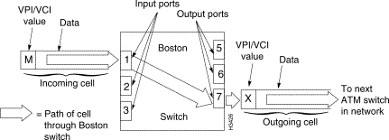
When the Boston switch receives an incoming cell on port 1 that carries the VPI/VCI value "M" in its header, it consults its internal routing table and finds that the VPI/VCI value M needs to be replaced with the value "X."
It finds further that the cell must be forwarded out of the switch from port 7. Accordingly, the outgoing cell is transmitted to the next switch in the network. This switching and table lookup process is illustrated in Figure 1-18.
In general, the cell transport process within an ATM network can be summarized as follows:
This process continues across network links until the ATM cell reaches its destination.
In accomplishing cell transport functions, ATM technology makes use of networking constructs called virtual channel connections (VCCs) and virtual paths (VPs). These constructs are described in the following sections.
A virtual channel (VC) is a logical circuit created to ensure reliable communications between two endpoints in an ATM network. For purposes of ATM cell transmission, a virtual channel connection (VCC) is regarded as an end-to-end connection for a single data flow between two nodes. A virtual channel is defined by the combination of the VPI field and the VCI field in the ATM cell header (see Figure 1-5).
ATM networking requires that you establish a connection between ATM endpoints. Because ATM is a connection-oriented technology, no information can be transferred from one endpoint in the network to another until such a connection is established.
In an LS2020 network, you pre-provision virtual connections (assign them manually beforehand) to meet a predictable, standing need for network bandwidth capacity. This type of connection endures until changed and is referred to as a permanent virtual connection (PVC).
Ordinarily, PVCs are established in a user's network at service subscription time, or at network configuration time, through the manual provisioning process mentioned above. However, these connections can be changed by a subsequent provisioning process or by means of a customer network management application.
In a typical ATM cell switching environment, a VCC consists of a concatenation of virtual channel links (VCLs), each of which serves as a means of bidirectional transport of ATM cells. Figure 1-19 illustrates a simple VCC consisting of two VCLs, although many such VCLs often exist in an actual ATM communications application.
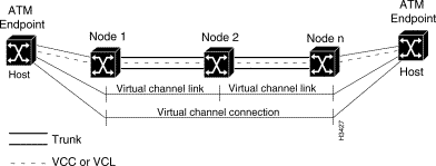
The virtual channel identifier (VCI) in each ATM cell header identifies the VCL through which a cell must pass. Thus, in effect, a concatenation of VCLs sets up a communications path through which ATM cells flow between network endpoints. A connection from a local LS2020 switch to a central office that, in turn, is connected to another LS2020 switch is an example of a simple two-link VCC.
All communications between two network endpoints can occur by means of the same VCC. Such a connection preserves the sequence of ATM cells being transmitted between the endpoints and guarantees a certain level or quality of service. ATM cells may also be transported within virtual paths (VPs), as described in the following section.
A VP is identified solely by the VPI field in the ATM cell header (see Figure 1-5); for VP purposes, the VCI field in the header is ignored.
From the viewpoint of the network, an ATM cell is either a VP cell or a VC cell. If a cell traversing the network is a VP cell, the network pays attention to the VPI field in the cell header; similarly, if a cell traversing the network is a VC cell, the network pays attention to the VCI field.
Two fundamental advantages derive from VPs in a network:
The practical advantage of VPs in an ATM network is that they enable cell streams from multiple users to be bundled together into a higher-rate signal on the same physical link for transport through the network. Figure 1-20 illustrates this principle.
Thus, VPs provide a convenient way of handling traffic being directed to the same destination in the network. VPs are also useful in handling traffic that requires the same quality of service (QoS). For these reasons, VPs are typically used in ATM networks for trunking purposes.

This section describes the ATM UNI interface types and the ATM addressing scheme used in establishing virtual connections in an ATM network.
ATM networks often pass information of different types. Furthermore, the types of connections set up between communicating peers can vary according to the network's end-to-end topology and its underlying nature.
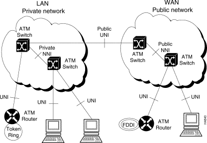
For example, an ATM network may encompass a local workgroup, an enterprise network, a public or private network, or some combination of these domains. Accordingly, the interfaces between these domains vary, as described below:
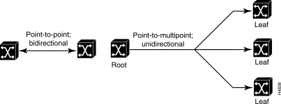
Figure 1-21 illustrates the interface types common to ATM networks.
The ATM Forum agreed that all ATM equipment would identify ATM endpoints using what is known as the OSI Network Services Access Point (NSAP) addressing format. An NSAP address represents that point in a network at which OSI network services are provided to a transport layer (layer 4) entity. The ATM private network address formats are described in the following section.
Several address formats, or ATM endpoint identifiers, have been specified by the ATM Forum for use in private ATM networks. These 20-byte address formats are illustrated in Figure 1-22.
All NSAP format ATM addresses consist of three components:
The three private network address formats are described briefly below:
These three private network addresses can be specific to a local country or they can be globally unique.
In ATM LANs, an ATM endpoint's IEEE MAC (media access control) address will most likely be used as the End System Identifier (ESI). See Figure 1-22. Therefore, when an ATM endstation connects to a network for the first time, it must register its MAC address with an address registration service provided by the ATM network. The address registration service then responds to the endstation with its assigned NSAP address and stores its MAC-to-ATM address pairs with the respective switch and port number.
The address registration service is accessed and maintained by means of the Interim Local Management Interface (ILMI), which facilitates auto-configuration of an ATM endpoint's NSAP address.
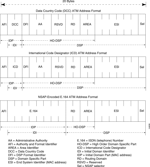
Public ATM networks use a telephone number-like E.164 address that is formatted as specified by the ITU-T. This format is typically used in today's public telephony networks. E.164 addresses, being a public (and expensive) resource, are ordinarily not used in private ATM networks.
Note, however, that public ATM networks can use an NSAP-encoded addressing format that incorporates an E.164-like address, as shown in Figure 1-22. This format is ordinarily used for encoding E.164 addresses in private networks, but it may also be used in public networks.
![]()
![]()
![]()
![]()
![]()
![]()
![]()
![]()
Posted: Wed Oct 2 06:05:44 PDT 2002
All contents are Copyright © 1992--2002 Cisco Systems, Inc. All rights reserved.
Important Notices and Privacy Statement.