|
|

Table Of Contents
Displaying the Template Alias Configuration
Configuring an ATM Filter Expression
Configuring ATM Interface Access Control
Displaying ATM Filter Configuration
ATM Filter Configuration Scenario
Filtering IP Packets at the IP Interfaces
Creating Standard and Extended IP Access Lists
Applying an IP Access List to an Interface or Terminal Line
Configuring Per-Interface Address Registration with Optional Access Filters
Displaying the ILMI Access Filter Configuration
Using Access Control
This chapter describes how to configure and maintain access control lists, which are used to permit or deny incoming calls or outgoing calls on an interface of the ATM switch router.
Note
This chapter provides advanced configuration instructions for the Catalyst 8540 MSR, Catalyst 8510 MSR, and LightStream 1010 ATM switch routers. For complete descriptions of the commands mentioned in this chapter, refer to the ATM Switch Router Command Reference publication.
This chapter includes the following sections:
•
•
•
•
•
•
Access Control Overview
The ATM signalling software uses the access control list to filter setup messages on an interface based on destination, source, or a combination of both. Access lists can be used to deny connections known to be security risks and permit all other connections, or to permit only those connections considered acceptable and deny all the rest. For firewall implementation, denying access to security risks offers more control.
During initial configuration, perform the following steps to use access control to filter setup messages:
Step 1
Step 2
Step 3
Step 4
Configuring a Template Alias
To configure an ATM template alias, use the following command in global configuration mode:
Examples
The following example creates a template alias named training using the ATM address template 47.1328 and the ellipses (...) to fill in the trailing 4-bit hexadecimal digits in the address:
Switch(config)# atm template-alias training 47.1328...The following example creates a template alias named bit_set with the ATM address template 47.9f9.(1*0*).88ab... that matches the four addresses that begin with the following:
•
•
•
•
Switch(config)# atm template-alias bit_set 47.9f9(1*0*).88ab...The following example creates a template alias named byte_wise with the ATM address template 47.9*F8.33... that matches all ATM addresses beginning with the following sixteen prefixes:
•
through
•
Switch(config)# atm template-alias byte_wise 47.9*F8.33...Displaying the Template Alias Configuration
To display template alias configuration, use the following privileged EXEC command:
Example
The following example shows the template aliases configured in the previous examples using the more system:running-config privileged EXEC command:
Switch# more system:running-configBuilding configuration...Current configuration:!version XX.Xno service padservice udp-small-serversservice tcp-small-servers!hostname Switch!!username dtateip rcmd remote-username dplatzatm template-alias training 47.1328...atm template-alias bit_set 47.9f9(1*0*).88ab...atm template-alias byte_wise 47.9*f8.33...!<information deleted>Configuring ATM Filter Sets
To create an ATM address filter or time-of-day filter, use the following command in global configuration mode:
atm filter-set name [index number] [permit | deny] {template | time-of-day {anytime | start-time end-time}}
Configures a global ATM address filter set.
Examples
The following example creates a filter named filter_1 that permits access to the specific ATM address 47.0000.8100.1234.0003.c386.b301.0003.c386.b301.00:
Switch(config)# atm filter-set filter_1 permit 47.0000.8100.1234.0003.c386.b301.0003.c386.b301.00The following example creates a filter named filter_2 that denies access to the specific ATM address 47.000.8100.5678.0003.c386.b301.0003.c386.b301.00, but allows access to all other ATM addresses:
Switch(config)# atm filter-set filter_2 deny 47.0000.8100.5678.0003.c386.b301.0003.c386.b301.00Switch(config)# atm filter-set filter_2 permit defaultThe following example creates a filter named filter_3 that denies access to all ATM addresses that begin with the prefix 47.840F, but permits all other calls:
Switch(config)# atm filter-set filter_3 deny 47.840F...Switch(config)# atm filter-set filter_3 permit default
Note
In the following example, the first filter set, filter_4, has its first filter configured to permit all addresses and its second filter configured to deny access to all addressees that begin with the prefix 47.840F. Since the default filter matches all addresses, the second filter is never used. Addresses that begin with prefix 47.840F are also permitted.
Switch(config)# atm filter-set filter_4 permit defaultSwitch(config)# atm filter-set filter_4 deny 47.840F...The following example creates a filter named filter_5 that denies access to all ATM addresses described by the ATM template alias bad_users:
Switch(config)# atm filter-set filter_5 deny bad_usersSwitch(config)# atm filter-set filter_5 permit defaultThe following example shows how to configure a filter set named tod1, with an index of 2, to deny calls between 11:15 a.m. and 10:45 p.m.:
Switch(config)# atm filter-set tod1 index 2 deny time-of-day 11:15 22:45Switch(config)# atm filter-set tod1 index 3 permit time-of-day anytimeThe following example shows how to configure a filter set named tod1, with an index of 4, to permit calls any time:
Switch(config)# atm filter-set tod1 index 4 permit time-of-day anytimeThe following example shows how to configure a filter set named tod2 to deny calls between 8:00 p.m. and 6:00 a.m.:
Switch(config)# atm filter-set tod2 deny time-of-day 20:00 06:00Switch(config)# atm filter-set tod2 permit time-of-day anytimeThe following example shows how to configure a filter set named tod2 to permit calls at any time:
Switch(config)# atm filter-set tod2 permit time-of-day 3:30 3:30Once you create a filter set using the previous configuration commands, it must be associated with an interface as an access group to actually filter any calls. See the "Configuring ATM Interface Access Control" section to configure an individual interface with an access group.
Deleting Filter Sets
To delete an ATM filter set, use the following command in global configuration mode:
Example
The following example shows how to display and delete filter sets:
Switch# show atm filter-setATM filter set tod1deny From 11:15 Hrs Till 22:45 Hrs index 2permit From 0:0 Hrs Till 0:0 Hrs index 4ATM filter set tod2deny From 20:0 Hrs Till 6:0 Hrs index 1permit From 3:30 Hrs Till 3:30 Hrs index 2Switch# configure terminalEnter configuration commands, one per line. End with CNTL/Z.Switch(config)# no atm filter-set tod1 index 2Switch(config)# no atm filter-set tod2Switch(config)# endSwitch#%SYS-5-CONFIG_I: Configured from console by consoleSwitch# show atm filter-setATM filter set tod1permit From 0:0 Hrs Till 0:0 Hrs index 4Configuring an ATM Filter Expression
To create global ATM filter expressions, perform the following steps in global configuration mode:
Examples
The following example defines a simple filter expression that has only one term and no operators:
Switch(config)# atm filter-expr training filter_1The following example defines a filter expression using the operator not:
Switch(config)# atm filter-expr training not filter_1The following example defines a filter expression using the operator or:
Switch(config)# atm filter-expr training filter_2 or filter_1The following example defines a filter expression using the operator and:
Switch(config)# atm filter-expr training filter_1 and source filter_2The following example defines a filter expression using the operator xor:
Switch(config)# atm filter-expr training filter_2 xor filter_1Configuring ATM Interface Access Control
To subscribe an ATM interface or subinterface to an existing ATM filter set or filter expression, perform the following steps, beginning in global configuration mode:
Examples
The following example shows how to configure access control for outgoing calls on ATM interface 3/0/0:
Switch(config)# interface atm 3/0/0Switch(config-if)# atm access-group training out
The following example shows how to configure access control for both outgoing and incoming calls on ATM interface 3/0/0:
Switch(config)# interface atm 3/0/0Switch(config-if)# atm access-group training out
Switch(config-if)# atm access-group marketing inDisplaying ATM Filter Configuration
To display access control configuration, use the following EXEC commands:
show atm filter-set [name]
Displays a specific or a summary of ATM filter set.
show atm filter-expr [detail] name
Displays a specific or a summary of ATM filter expression.
Examples
The following command displays the configured ATM filters:
Switch# show atm filter-setATM filter set tod1deny From 11:15 Hrs Till 22:45 Hrs index 2permit From 0:0 Hrs Till 0:0 Hrs index 4ATM filter set tod2deny From 20:0 Hrs Till 6:0 Hrs index 1permit From 3:30 Hrs Till 3:30 Hrs index 2The following command displays the configured ATM filter expressions:
Switch# show atm filter-exprtraining = dest filter_1ATM Filter Configuration Scenario
This section provides a complete access filter configuration example using the information described in the preceding sections.
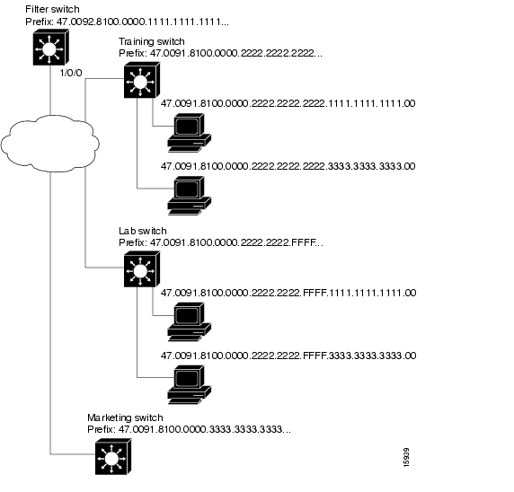
The example network configuration used in the following filter set configuration scenario is shown in Figure 11-1.
Figure 11-1 ATM Access Filter Configuration Example
Example
The following example shows how to configure the Filter Switch, shown in Figure 11-1, to deny access to all calls received on ATM interface 1/0/0 from the workstations directly attached to the Lab Switch, but to allow all other calls. The Filter Switch denies all calls if the calling party address begins with the prefix 47.0091.8100.0000.2222.2222.FFFF:
Filter Switch(config)# atm template-alias lab-sw 47.0091.8100.0000.2222.2222.FFFF...Filter Switch(config)# atm filter-set filter_1 deny lab-swFilter Switch(config)# atm filter-set filter_1 permit defaultFilter Switch(config)# atm filter-expr exp1 src filter_1Filter Switch(config)#Filter Switch(config)# interface atm 1/0/0Filter Switch(config-if)# atm access-group exp1 inFilter Switch(config-if)# endFilter Switch# show atm filter-setATM filter set filter_1deny 47.0091.8100.0000.2222.2222.ffff... index 1permit default index 2Filter Switch# show atm filter-exprexp1 = src filter_1Filtering IP Packets at the IP Interfaces
IP packet filtering helps control packet movement through the network. Such control can help limit network traffic and restrict network use by certain users or devices. To permit or deny packets from crossing specified IP interfaces, Cisco provides access lists.
You can use access lists for the following reasons:
•
•
•
This section summarizes how to create IP access lists and how to apply them.
Note
An access list is a sequential collection of permit and deny conditions that apply to IP addresses. The ATM switch router software tests addresses against the conditions in an access list one by one. The first match determines whether the software accepts or rejects the address. Because the software stops testing conditions after the first match, the order of the conditions is critical. If no conditions match, the software rejects the address.
The two steps involved in using access lists follow:
Step 1
Step 2
These steps are described in the following sections:
•
•
Creating Standard and Extended IP Access Lists
The ATM switch router software supports three styles of access lists for IP interfaces:
•
•
•
To create a standard access list, use one of the following commands in global configuration mode:
To create an extended access list, use one of the following commands in global configuration mode:
After you create an access list, any subsequent additions (possibly entered from the terminal) are placed at the end of the list. In other words, you cannot selectively add or remove access list command lines from a specific access list.
Note
Applying an IP Access List to an Interface or Terminal Line
After you create an access list, you can apply it to one or more interfaces. Access lists can be applied on either outbound or inbound interfaces. The following two tables show how this task is accomplished for both terminal lines and network interfaces.
To apply an access list to a terminal line, perform the following tasks, beginning in global configuration mode:
To apply an access list to a network interface, perform the following tasks, beginning in global configuration mode:
For inbound access lists, after receiving a packet, the ATM switch router software checks the source address of the packet against the access list. If the access list permits the address, the software continues to process the packet. If the access list rejects the address, the software discards the packet and returns an Internet Control Message Protocol (ICMP) host unreachable message.
For outbound access lists, after receiving and routing a packet to a controlled interface, the software checks the source address of the packet against the access list. If the access list permits the address, the software transmits the packet. If the access list rejects the address, the software discards the packet and returns an ICMP host unreachable message.
If you apply an access list (standard or extended) that has not yet been defined to an interface, the software acts as if the access list has not been applied to the interface and accepts all packets. You must define the access list to the interface if you use it as a means of security in your network.
Note
IP Access List Examples
In the following example, network 36.0.0.0 is a Class A network whose second octet specifies a subnet; that is, its subnet mask is 255.255.0.0. The third and fourth octets of a network 36.0.0.0 address specify a particular host.
Using access list 2, the ATM switch router software accepts one address on subnet 48 and rejects all others on that subnet. The last line of the list shows that the software accepts addresses on all other network 36.0.0.0 subnets.
Switch(config)# access-list 2 permit 36.48.0.3Switch(config)# access-list 2 deny 36.48.0.0 0.0.255.255Switch(config)# access-list 2 permit 36.0.0.0 0.255.255.255Switch(config)# interface ethernet0Switch(config-if)# ip access-group 2 inExamples of Implicit Masks in IP Access Lists
IP access lists contain implicit masks. For example, if you omit the mask from an associated IP host address access list specification, 0.0.0.0 is assumed to be the mask. Consider the following example configuration:
Switch(config)# access-list 1 permit 0.0.0.0Switch(config)# access-list 1 permit 131.108.0.0Switch(config)# access-list 1 deny 0.0.0.0 255.255.255.255For this example, the following masks are implied in the first two lines:
Switch(config)# access-list 1 permit 0.0.0.0 0.0.0.0Switch(config)# access-list 1 permit 131.108.0.0 0.0.0.0The last line in the configuration (using the deny keyword) can be omitted, because IP access lists implicitly deny all other access, which is equivalent to finishing the access list with the following command statement:
Switch(config)# access-list 1 deny 0.0.0.0 255.255.255.255The following access list only allows access for those hosts on the three specified networks. It assumes that subnetting is not used; the masks apply to the host portions of the network addresses. Any hosts with a source address that does not match the access list statements is rejected.
Switch(config)# access-list 1 permit 192.5.34.0 0.0.0.255Switch(config)# access-list 1 permit 128.88.0.0 0.0.255.255Switch(config)# access-list 1 permit 36.0.0.0 0.255.255.255! (Note: all other access implicitly denied)To specify a large number of individual addresses more easily, you can omit the address mask that is all zeros from the access-list global configuration command. Thus, the following two configuration commands are identical in effect:
Switch(config)# access-list 2 permit 36.48.0.3Switch(config)# access-list 2 permit 36.48.0.3 0.0.0.0Examples of Configuring Extended IP Access Lists
In the following example, the first line permits any incoming Transmission Control Protocol (TCP) connections with destination ports greater than 1023. The second line permits incoming TCP connections to the simple mail transfer protocol (SMTP) port of host 128.88.1.2. The last line permits incoming ICMP messages for error feedback.
Switch(config)# access-list 102 permit tcp 0.0.0.0 255.255.255.255 128.88.0.0 0.0.255.255 gt 1023Switch(config)# access-list 102 permit tcp 0.0.0.0 255.255.255.255 128.88.1.2 0.0.0.0 eq 25Switch(config)# access-list 102 permit icmp 0.0.0.0 255.255.255.255 128.88.0.0 255.255.255.255Switch(config)# interface ethernet0Switch(config-if)# ip access-group 102 inAs another example, suppose you have a network connected to the Internet, and you want any host on an Ethernet to be able to form TCP connections to any host on the Internet. However, you do not want IP hosts to be able to form TCP connections to hosts on the Ethernet except to the mail (SMTP) port of a dedicated mail host.
SMTP uses TCP port 25 on one end of the connection and a random port number on the other end. The same two port numbers are used throughout the life of the connection. Mail packets coming in from the Internet have a destination port of 25. Outbound packets will have the port numbers reversed. The fact that the secure system behind the switch always accepts mail connections on port 25 is what makes it possible to separately control incoming and outgoing services. The access list can be configured on either the outbound or inbound interface.
In the following example, the Ethernet network is a Class B network with the address 128.88.0.0, and the mail host's address is 128.88.1.2. The keyword established is used only for the TCP protocol to indicate an established connection. A match occurs if the TCP datagram has the acknowledgment (ACK) or RST bits set, indicating that the packet belongs to an existing connection.
Switch(config)# access-list 102 permit tcp 0.0.0.0 255.255.255.255 128.88.0.0 0.0.255.255 establishedSwitch(config)# access-list 102 permit tcp 0.0.0.0 255.255.255.255 128.88.1.2 0.0.0.0 eq 25Switch(config)# interface ethernet0Switch(config-if)# ip access-group 102 inConfiguring Per-Interface Address Registration with Optional Access Filters
The ATM switch router allows configuration of per-interface access filters for Integrated Local Management Interface (ILMI) address registration to override the global default of access filters.
To configure ILMI address registration and the optional access filters for a specified interface, perform the following tasks, beginning in global configuration mode:
Example
The following example shows how to configure ILMI address registration on an individual interface to permit all groups with a matching ATM address prefix:
Switch(config)# interface atm 3/0/0Switch(config-if)# atm address-registration permit matching-prefix all-groups%ATM-5-ILMIACCFILTER: New access filter setting will be applied to registrationof new addresses on ATM3/0/0.Switch(config-if)#Displaying the ILMI Access Filter Configuration
To display the interface ILMI address registration access filter configuration, use the following EXEC command:
more system:running-config
Displays the interface ILMI address registration access filter configuration.
Example
The following example displays address registration access filter configuration for ATM interface 3/0/0:
Switch# more system:running-configBuilding configuration...Current configuration:!version XX.Xno service pad<Information Deleted>interface ATM0no ip addressatm maxvp-number 0!interface Ethernet0ip address 172.20.41.110 255.255.255.0ip access-group 102 out!interface ATM3/0/0no atm auto-configurationatm address-registration permit matching-prefix all-groupsatm iisp side useratm pvc 100 200atm signalling cug access permit-unknown-cugs both-direction permanentatm accounting!interface ATM3/0/1!<information deleted>
![]()
![]()
![]()
![]()
![]()
![]()
![]()
![]()
Posted: Mon Oct 11 09:07:55 PDT 2004
All contents are Copyright © 1992--2004 Cisco Systems, Inc. All rights reserved.
Important Notices and Privacy Statement.