|
|

This chapter contains instructions for installing and initially configuring the LightStream 100 switch. Information about resetting the switch and the use of a console terminal with the switch is also provided. This information is provided in the following sections:
To properly install the LightStream 100, you will need the following equipment:
 | Caution Ensure all interface cables that connect to the LightStream 100 switch are shielded cables with ferrite cores and connectors with metallic shells at both ends. Use of other cable types may result in interference with radio and TV reception. |
This section provides complete installation instructions for an initial installation of the LightStream 100 switch. This section contains the following procedures:
Perform the following steps to remove the LightStream 100 ATM switch cover:
Step 1 Provide protection against static electricity.
Step 2 Confirm that the LightStream 100 switch power switch is in the OFF (O) position.
Step 3 Using a Phillips screwdriver, remove the six outer screws from the processor (PROC) card panel. Figure 3-1 shows the location of the screws on the PROC card panel.

Step 4 Grasp the card ejector levers on each end of the PROC card panel and pull the card outward.
Step 5 Turn the LightStream 100 switch on its side and then turn it upside down.
Step 6 Using a Phillips screwdriver, remove the seven outer screws from the bottom of the LightStream 100 switch. Figure 3-2 shows the location of the screws.
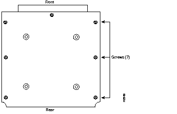
Step 7 Completely return the LightStream 100 switch to the upright position.
Step 8 Remove the outer screws from the rear panel of the LightStream 100 switch. Figure 2-2 shows the location of the screws.
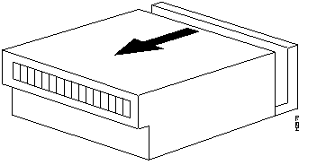
Step 9 Facing the front of the Lightstream 100 switch, hold both sides of the cover and slide it slightly forward (approximately 1 inch [25 millimeters]). (See Figure 3-3.)
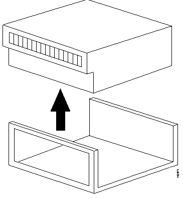
Step 10 Lift the cover upward. (See Figure 3-4.)
 | Caution If the LINF cards are already installed, lifting the cover before properly sliding it forward may damage the optical connector on the LINF cards. |
Locate the BCONV card and STS-3c/STM-1 LINF card. For each card, ensure that the dual in-line package (DIP) switches and jumpers settings are set to initial settings. All switches and jumpers are set at the factory.
Figure 3-5 shows the initial DIP switch setting on the BCONV card (P-8X54). If the switch setting differs from this setting, return it to the initial setting indicated in the figure.
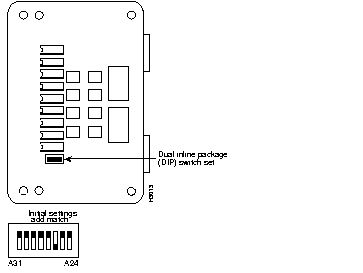
Figure 3-6 shows the initial settings for the motherboard (P-8X84) jumper switch. If the switch setting differs from this setting, return it to the initial setting indicated in the figure.
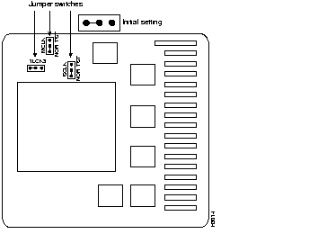
Figure 3-7 shows the initial setting for the STS-3c/STM-1 LINF card (P-8X79) jumper switch. If the switch setting differs from this setting, return it to the initial setting indicated in the figure.
This section describes the initial installation method for the two LINF card types: STS-3c/STM-1 (155 Mbps) and Transparent Asynchronous Transmitter/Receiver Interface (TAXI) (100 Mbps). Both card types install the same way. Before installing LINF cards, ensure that the power switch on the back of the LightStream 100 ATM switch is in the OFF (O) position.
Table 3-1 provides recommended mounting positions in the slots where LINF cards are installed, depending on the number of cards installed. If designating the LightStream 100 switch as a slave switch, install the STS-3c/STM-1 LINF card in Slot 0.
| Number of Interface Cards | Suggested Slot Mounting Locations |
|---|---|
| 1 | 0 |
| 2 | 0, 2 |
| 3 | 0, 2, 4 |
| 4 | 0, 2, 4, 6 |
| 5 | 0, 2, 4, 6, 8 |
| 6 | 0, 2, 4, 6, 8, 10 |
| 7 | 0, 2, 4, 6, 8, 10, 12 |
| 8 | 0, 2, 4, 6, 8, 10, 12, 14 |
| 9 | 0-2, 4, 6, 8, 10, 12, 14 |
| 10 | 0-...4, 6, 8, 10, 12, 14 |
| 11 | 0-......6, 8, 10, 12, 14 |
| 12 | 0-........8, 10, 12, 14 |
| 13 | 0-...........10, 12, 14 |
| 14 | 0-...............12, 14 |
| 15 | 0-...................14 |
| 16 | 0-......................15 |
Perform the following steps to install a LINF card:
Step 1 Remove the LINF card from the container.
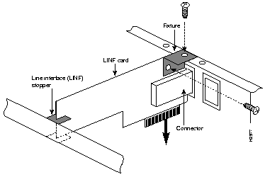
Step 2 Install the LINF card from the top of the slot. Ensure that the LINF card is securely fixed to the LINF stopper at the rear of the LightStream 100 switch main unit.
Step 3 Match the screw holes on the LINF card with the screw holes on the LightStream 100 switch. Insert the screws and secure them using a standard screwdriver. (See Figure 3-8.)
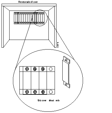
Step 4 From the inside of the cover, remove the slot cover (without window) from the slot where the LINF card is installed. Use a Phillips screwdriver to remove the two screws (at top and bottom) that fasten the front panel on the opposite side of the cover. (See Figure 3-9.)
Step 5 Install the slot cover (with window) and fasten it to the cover with the two screws you removed in step 4. Ensure the slot cover is right side up.
Perform the following steps to replace the LightStream 100 ATM switch cover:
Step 1 Put the cover on the base starting approximately 1 inch (25 millimeters) from the front. Then slide the cover back until the screw holes align.
Step 2 Using a Phillips screwdriver, replace the screws on the rear panel of the LightStream 100 switch.
Step 3 Turn the LightStream 100 switch on its side and then turn it upside down.
Step 4 Replace the seven outer screws on the bottom of the LightStream 100 switch.
Step 5 Return the LightStream 100 switch to the upright position.
Step 6 Grasp the card ejectors on the PROC card panel and insert the card into the LightStream 100 switch front panel.
Step 7 Replace the six outer screws that secure the PROC card panel to the chassis.
This section provides the procedure for rack-mounting the LightStream 100 ATM switch.
To rack-mount the LightStream 100 switch, perform the following procedure:
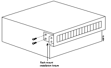
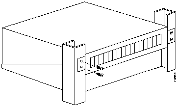
Step 1 Attach the rack-mount installation fixtures with screws on both sides of the LightStream 100 main unit. (See Figure 3-10.)
Step 2 Slide the LightStream 100 main unit into the rack by pushing it toward the front of the rack.
Step 3 Use screws to fasten the LightStream 100 switch to the rack-mount fixture. (See Figure 3-11.)
This section provides the procedure for connecting optical cables to the LINF cards installed in the LightStream 100 ATM switch. The LINF cards have two connectors: the upper optical connector is for reception, and the lower one is for transmission. Use a single-core or two-core optical cable to connect the LINF cards installed on the LightStream 100 switch. Figure 3-12 shows the single-core and two-core cables.
 | Caution Ensure all interface cables that connect to the LightStream 100 switch are shielded cables with ferrite cores and connectors with metallic shells at both ends. Other cable types can cause interference with radio and TV reception. |

When using a single-core optical cable, ensure that the transmission end connects to the reception connector of one device and that the reception end connects to the transmission connector of the other device. Use the appropriate two-core cable, straight (A-C, B-D connections) or cross (A-D, B-C connections). When connecting two or more LightStream 100 switch units with the two-core cable, use cross-cable connection.
To connect optical cables, perform the following procedure:
Step 1 Have enough optical cables to accommodate the LINF card type and quantity.
Step 2 Connect the appropriate optical cable to the slot cover (with window) of the slot where the LINF card is installed.
This section provides the procedure for connecting an EIA/TIA-232 cable to the LightStream 100 ATM switch. To connect the cable, do the following:
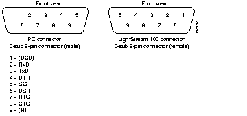
Step 1 The EIA/TIA-232 connector for the console terminal configuration differs for each console terminal device. Use an EIA/TIA-232 cable that has a connector matching the console terminal on one end and a connector with D-sub 9-pin male connector for the LightStream 100 switch on the other end. Figure 3-13 shows connectors for an IBM-compatible PC and the LightStream 100 switch.
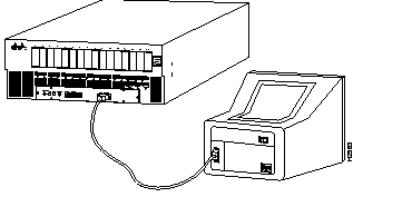
Step 2 Connect the EIA/TIA-232 cable (9-pin end) to the EIA/TIA-232 connector on the front of the LightStream 100 switch. See Figure 3-14.
Step 3 Connect the other end of the EIA/TIA-232 cable to the console terminal.
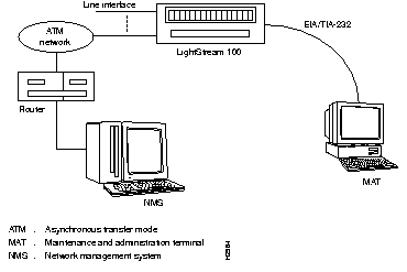
Using the Simple Network Management Protocol (SNMP) over User Datagram Protocol (UDP)/Internet Protocol (IP) ATM Adaptation Layer 5 (AAL5), the LightStream 100 ATM switch communicates with the Network Management System (NMS) manager via an ATM line. Figure 3-15 shows the connection of the LightStream 100 switch to the console terminal and the NMS. Refer to the router software configuration publications to configure the interface between the LightStream 100 switch and the NMS.
Complete the tasks described in the preceding sections before connecting the power cable to the LightStream 100 ATM switch and turning the power ON.
 | Warning Do not touch the power supply when the power cord is connected. For systems with a power switch, line voltages are present within the power supply even when the power switch is off and the power cord is connected. For systems without a power switch, line voltages are present within the power supply when the power cord is connected. To see this warning in multiple languages, refer to the "Translated Safety Warnings" appendix. |
 | Caution Use an uninterruptible power supply (UPS) power system to prevent system outage in case of a commercial power failure. |
To connect the power supply cable, follow these steps:
Step 1 Connect one end of the power supply cable to the power connector on the back of the LightStream 100 switch.
Step 2 Plug the other end of the power supply cable into a power outlet.
 | Caution Never use an adapter to share the power outlet used for the LightStream 100 switch with another electrical device. |
Step 3 Set the power switch on back of the LightStream 100 switch to the ON (|) position.
Step 4 Ensure the green Power light emitting diode (LED) on the front of the LightStream 100 switch lights up.
Step 5 Set the power switch on the back of the LightStream 100 switch to the OFF (O) position.
To connect the console terminal power supply, plug the console terminal power cord into a power outlet. Refer to the documentation provided with the console terminal for additional information.
A self-diagnostic test runs when the LightStream 100 switch is powered ON or reset. The results display on the console terminal.
To power OFF the LightStream 100 switch, set the power switch to the OFF (O) position. The Power LED goes OFF.
When a PC or workstation is used as the console terminal, you can install communications software to set the interface for easier automatic control. No communications software is necessary if the PC or workstation operates in terminal mode. However, we recommend installing communications software on the console terminal to simplify operations.
To set communications software parameters, perform the following procedure:
Step 1 Make sure that the LightStream 100 ATM switch power is OFF.
Step 2 Set the console terminal power switch to the ON (|) position.
Step 3 Set the following communications parameters on the console terminal:
To power on the LightStream 100 ATM switch, perform the following procedure:
Step 1 Set the power switch on back of the LightStream 100 switch to the ON (|) position.
Step 2 The LightStream 100 switch starts to execute a self-diagnostic test. The results show on the console terminal. If a fault occurs, the Alarm LED lights up.
Step 3 Ensure that the red alarm LED does not light up. If an alarm occurs, refer to the chapter "Troubleshooting" for instructions about clearing the alarm.
Step 4 Confirm that no hardware configuration item indicates "NG" (No Good) and that "Not Installed" does not appear for a slot in which the LINF card is installed.
This section explains an initial system configuration. Refer to the appendix "Command Reference" for detailed information about the commands used in the configuration procedure.
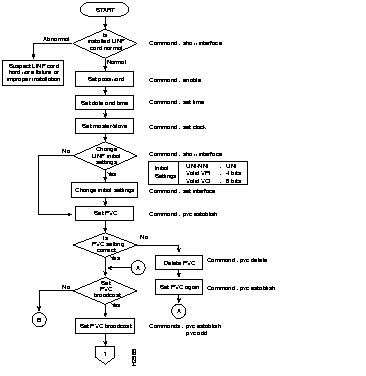
Figure 3-16 and Figure 3-17 show two parts of a flowchart of the configuration data setting procedure. The flowchart corresponds to the actions in the following procedure:
Step 1 Enter the show interface command to display data for LINF cards installed in the LightStream 100 switch. Make sure the line number of the newly installed LINF card is displayed. If the line number is not displayed, either the LINF card is improperly installed or LINF hardware error exists. Turn OFF the LightStream 100 switch power and check the card.
Step 2 Enter the enable command to enter privileged command mode. The system requests a password.
Step 3 Enter lowercase c. The prompt changes from > to #.
Step 4 Enter the set time command to set the date and time of the LightStream 100 switch system clock. Separate year, month, and day with a hyphen (-); separate hour, minute, and second with a colon (:). The following example shows how to set the time to 18:30:00 on April 1, 1994:
set time 94-04-01 18:30:00
Step 5 Enter the set clock command to set the clock synchronization mode. When a LightStream 100 switch unit is connected to another LightStream 100 switch unit or to a different type of device, this function designates the LightStream 100 switch as a master or slave unit.
Step 6 Enter the set interface command to register a line. This command can change the following initial setting of a line:
Step 7 Enter the pvc establish command to set a point-to-point Permanent Virtual Circuit (PVC). This command becomes effective immediately after it is set.
Step 8 If setting PVC multicast, enter the following commands:
Step 9 If using SVC service, enter the route add command to set the SVC.
Step 10 If an NMS is connected to the LightStream 100 switch for control using SNMP, enter the following commands:
Step 11 Enter the save command to save the configuration data.
Step 12 Enter the exit command to exit privileged command mode. The prompt changes from # to >.
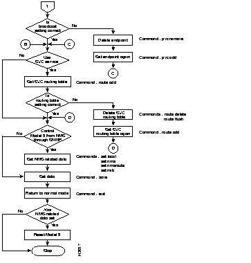
When NMS-related commands are set, always save the data, exit the privileged mode, and enter the reset command or press the Reset button on the LightStream 100 ATM switch front panel.
When verification detects no abnormality, the LightStream 100 ATM switch is ready for normal operation.
The LightStream 100 switch does not require a console terminal for normal operation. If the console terminal is dedicated to operating and administering the LightStream 100 switch, do not disconnect it. However, if the console terminal is used for other purposes, remove the EIA/TIA-232 connector to disconnect the console terminal from the LightStream 100 switch.
|
|