|
|

The LightStream 100 switch is a desktop Asynchronous Transfer Mode (ATM) switch used to build workgroup local area networks (LANs) or a campus backbone switched internetwork. The LightStream 100 switch supports up to 16 ATM lines at 155 Mbps (megabits per second).
The LightStream 100 switch features an input and output buffer-type switch that provides an aggregate throughput of 2.5 gigabits per second (Gbps) (155 Mbps ¥ 16). The LightStream 100 switch complies fully with the ATM Forum ATM User-Network Interface Specification, Version 3.0, 9/10/1993, International Telecommunication Union Telecommunication Standardization Sector (ITU-T), and European Telecommunications Standards Institute (ETSI) specifications and recommendations.
The switch core, called the expandable ATM output-buffer modular switch (XATOMSW), features large-capacity buffering to guarantee quality of service in handling multimedia traffic. Because one line interface card serves one line, adding and changing the line terminating function can occur on a per-line basis.
Different interface types can be mixed on a LightStream 100 ATM switch used as either a backbone, workgroup, or wide-area network (WAN) access switch. Table 1-1 lists the interface types that are available.
| Physical Layer | Data Rate | Media | Connector |
|---|---|---|---|
| STS-3c/STM-11 | 155 Mbps | Multimode fiber2 | SC |
| STS-3c/STM-1 | 155 Mbps | Single-mode fiber | SC |
| STS-3c/STM-1 | 155 Mbps | UTP-53 | RJ-45 |
| TAXI4 4B/5B | 100 Mbps | Multimode fiber | MIC5 (FDDI6 type) |
| DS3/T3 | 45 Mbps | Coaxial cable | BNC |
| E3 | 34 Mbps | Coaxial cable | BNC |
Table 1-2 lists the LightStream 100 ATM switch specifications.
| Device | Component | Specification |
|---|---|---|
| Switch | Switch architecture | Input and output buffer type |
| Switch capacity | 2.5 Gbps (155 Mbps x 16) | |
| Buffer | Input buffer: 2048 cells per two lines
Output buffer: 128 cells per two lines | |
| Cell delay | 20 microseconds to 5 milliseconds | |
| Control system | Control processor | Internal 32-bit RISC1 processor |
| Number of concurrent connectable channels | 4096 channels per line (VP/VC2 routing supported)
All 12 bits of VPI3 (2x) Lower (12-x) bits of 16 bits of VCI4 | |
| NMS interface | SNMP5 | |
| Console terminal interface | EIA/TIA-2326 | |
| Ethernet interface | DB-15 | |
| Traffic control | Policing control | Peak cell rate can be set per connection |
| Congestion control | Back pressure: output line --> switch --> input line | |
| Priority control | Cell loss: Two levels
Cell delay: Two levels | |
| Line | Maximum line speed | 155 Mbps per line |
| Maximum number of lines per switch | 16 lines | |
| Interface types | SONET STS-3c/STM-1, multimode fiber (155 Mbps)
SONET STS-3c/STM-1, single-mode fiber (155 Mbps) STS-3c-STM-1, UTP-5 (155 Mbps) TAXI 4B/5B, multimode fiber, MIC (FDDI type, 100 Mbps) DS3/T3, BNC (45 Mbps) E3, BNC (34 Mbps) |
Table 1-3 lists the LightStream 100 ATM switch physical specifications.
The LightStream 100 ATM switch conforms to the product criteria in Table 1-4.
The LightStream 100 ATM switch provides the following features:
The LightStream 100 ATM switch is designed primarily for constructing ATM workgroup and campus backbone networks (see Figure 1-1) that connect a number of ATM routers, multilayer switches, and high-performance servers into a router cluster. ATM routers allow existing LANs to be interconnected across ATM backbones while paving the way for new applications, such as virtual LAN internetworking.
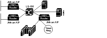
A router cluster can scale to many gigabits of bandwidth and millions of packets per second to alleviate the congestion on the backbone networks by allowing migration from the existing backbone technologies. While a router ATM interface module provides for transparent internetworking of current LAN and WAN protocols across the ATM backbone, high-speed servers can also be directly connected to the LightStream 100 switch, linking with desktop clients on multilayer switches through virtual LAN protocols.
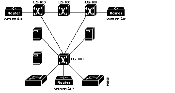
As network backbones increase in size, multiple switches can be interconnected to increase the scale and port density of the backbone. ATM routing protocols such as the Private Network-to-Node (PNNI) protocol currently being developed by the ATM Forum will be used to facilitate the construction of these large-scale ATM backbone networks. (See Figure 1-2.)
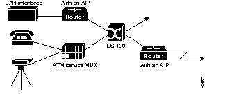
The LightStream 100 switch can also be used to build core and WAN access networks, supporting a heterogeneous mixture of cell, packet, and time-division multiplexing (TDM) trunk interfaces. (See Figure 1-3.) With the LightStream 100 switch as the core interconnect, ATM routers can be used to support the packet WAN and LAN interfaces, while ATM service multiplexers can support voice and video interfaces. In this way, a flexible solution can be deployed.
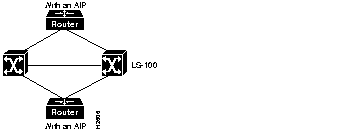
Reliable backup network configurations are possible with the LightStream 100 switch through the use of redundant network connections. (See Figure 1-4.) The LightStream 100 switch will automatically tear down any switched virtual connections through a failed link, allowing end systems to resignal for a new connection while bypassing the failed link. Cisco ATM routers can also support dual-homed connections and route around failed links, thus providing the same level of reliability on ATM backbones that can currently be achieved using router backbones.
The LightStream 100 ATM switch supports a wide range of LAN and WAN ATM interfaces. All interfaces conform to the relevant applicable standards, including those of the ATM Forum, ETSI, T1S1.5, and the ITU-T.
Because the LightStream 100 switch is designed for workgroup and campus backbone deployment, it supports such WAN interfaces as DS3, E3, and single-mode fiber Synchronous Optical Network/Synchronous Digital Hierarchy (SONET/SDH). This capability allows seamless connectivity between the ATM campus backbone and ATM public and private WANs. In workgroups, the LightStream 100 switch supports power users with direct ATM desktop interfaces. To facilitate such deployment, the LightStream 100 switch supports the ATM Forum copper (UTP-5) interfaces.
The relevant aspects of the ITU-T specifications are listed in Table 1-5.
| Number | Topic |
|---|---|
| G.707 | SDH speeds |
| G.708 | SDH basic frame structure |
| G.709 | SDH detailed frame structure |
| G.782 | SDH multiplexer types and general characteristics |
| G.783 | SDH multiplexer characteristics |
| G.7XX | ATM cell mapping into SDH |
| G.803 | Transmission network architecture |
| G.82X | Code error rules in physical layer |
| G.93B | B-ISDN subscriber line signal Layer 3 |
| G.96X | B-ISDN digital section |
| I.113 | B-ISDN terminology |
| I.121I | B-ISDN basic principles |
| I.150 | B-ISDN ATM functionality |
| I.211 | B-ISDN services |
| I.311 | B-ISDN network side, signaling principles |
| I.321 | B-ISDN protocol reference model and application |
| I.327 | B-ISDN functional structure |
| I.35B | B-ISDN ATM layer cell transfer function |
| I.361 | B-ISDN ATM layer specifications |
| I.362 | B-ISDN AAL1 functions |
| I.363 | B-ISDN AAL specifications |
| I.364 | B-ISDN connectionless services |
| I.371 | B-ISDN traffic control and congestion control |
| I.413 | B-ISDN user network interface |
| I.414 | ISDN and B-ISDN: concept of recommendations on user access in Layer 1 |
| I.432 | B-ISDN user network interface Layer 1 specifications |
| I.580 | B-ISDN and 64 Kbps internetworking |
| I.610 | B-ISDN OAM2 principles |
| Q.2931 | B-ISDN signaling Layer 3 |
| (Old Q.93B) | Q.2100 (Old Q.SAAL0)B-ISDN: concept of AAL for signaling |
| Q.2110 (Old Q.SAAL1) | B-ISDN: AAL SSSCOP3 for signaling |
| Q.2130 (Old Q.SAAL2) | B-ISDN: AAL SSCP4 for UNI signaling |
| Q.2140 (Old Q.SAAL3) | B-ISDN: AAL SSCP for NNI5 signaling |
The LightStream 100 ATM switch has three primary functions:
Following is a description of the cell switching function along the flow of ATM cells.
The line interface (LINF) card receives a cell sent over a line. A header translator checks the header error check (HEC) in the cell header and generates internal switch-specific overhead (SSO) information using VPI, VCI, and payload type (PT) in the cell header. The LINF inserts new VPI and VCI values in the cell header if the cell belongs to a point-to-point connection. The SSO transfers to the Expandable ATM output-buffer modular switch (XATOMSW) along with the cell.
The XATOMSW switches and sends the cell and SSO to the destination LINF according to the SSO information. When a specific line is congested, the system temporarily saves overflow cells in a 2048-cell input buffer and a 128-cell output buffer. Two lines share a buffer pool.
The LINF inserts new VPI and VCI values in the cell header according to information in the SSO after receiving the cell and SSO if the cell belongs to a point-to-multipoint connection.
This series of events results in cell transmission to the destination line.
This section describes policing control, congestion control, priority control, and monitoring items.
The LINF monitors each connection and discards any cell in excess of the preconfigured peak rate (set in advance). This policing control, known as usage parameter control (UPC), prevents any connection from unjustly dominating the switch bandwidth.
A peak transmission rate is set per connection; once a peak rate is exceeded, the LINF discards excess cells (if configured to do so with the pvc establish command). Specifically, the LINF counts the number of cells received per channel over a period of cell time (T) before the present moment. When the number of cells received over T exceeds a configured threshold (P), the system discards further cells.
The range of the cell time window (T) is 512 through 61,440. The cell time window (T) is divided into units of 512. Dividing the 61,440 window size into units of 512 yields 120 units.
The measurement period can be specified in units of 1 through 120. Each unit represents a window time of 512 cells. The usage parameter value peak (UPVP) represents the number of cells within a measurement period. The peak value equals the UPVP x unit. The measurement period within the window is Nw. P4 of the set tparam command sets Nw (see the section "set tparam" in the appendix "Command Reference"). Figure 1-5 shows the traffic measurement period formula:
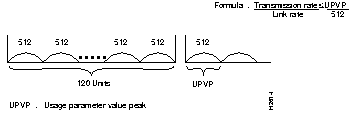
In the LightStream 100 ATM switch, a form of port congestion control takes place by applying a back pressure (BP) to restrict the number of input cells. The following format shows the direction that BP is applied:
Output line --> switch --> input buffer
Either high priority or low priority can be established for cell loss and cell delay on a per-connection basis. For cell delay, control is performed per the predetermined priority at connection setup phase. For cell loss, control is performed per the value of the Cell Loss Priority (CLP) bit in the cell header. The system handles a cell for which the CLP bit in the header is set to 0 as high loss priority and during congestion will discard CLP bits set to 1 first.
In the switch, a cell delay of 20 microseconds to 5 milliseconds occurs, depending on the degree of congestion and degree of priority of the passing cells. Priority on the delay can be set according to cell type:
In the LightStream 100 switch, two lines share one input buffer pool (2048 cells). The maximum size allowed for guaranteed cells, best effort cells, and CLP threshold can be set in 128-cell increments for this input buffer. (Smaller cell increments will be supported in future software releases.) This setting applies to the entire LightStream 100 switch; a different parameter cannot be set for each input buffer.
The LightStream 100 switch performs resource allocation and path establishment when a PVC or SVC setup request occurs.
The number of VPI and VCI bits necessary for ATM connection are configured per line. A total of 12 bits is supported for VPI and VCI (up to 4096 channels per line). Because VPIs/VCIs are distributed to PVC and SVC, when using SVC, the number of available PVCs diminishes accordingly.
The LightStream 100 switch supports 12 bits of VPI/VCI address space:
The LightStream 100 switch can have both point-to-point and point-to-multipoint connections. The following list indicates the current number of each connection type per system. The number of point-to-point connections does not decrease if the maximum number of point-to-multipoint connections are established, and vice versa. The number of possible PVCs and SVCs follow:
Entering commands at the console terminal can establish or disconnect connections and can add endpoints on a point-to-multipoint connection. Registering a PVC setting automatically establishes the registered PVC. A command from the console terminal or a GET request from the NMS displays connection information. The LightStream 100 switch controls the following items for each PVC connection:
Use the console terminal to make additions and deletions of PVC entries and PVC connection information saved in Flash memory. Upon system reset, control (CTL) initializes the header translator table in each LINF and the multicast bit-map table in the XATOMSW according to the PVC information saved in Flash memory.
To shorten the time-consuming and error-prone task of end-to-end manual configuration of PVCs, the LightStream 100 switch supports soft PVC/PVP. With soft PVC/PVP support, you can create a PVC across a multiswitch network by designating only the two endpoints of the connection. The software dynamically establishes a connection between those points, eliminating manual configuration of the switches between the two endpoints. Without soft PVC/PVP support, every link in the path between the two ATM hosts must be manually configured as a PVC. By reducing manual configuration, soft PVC/PVP can save you considerable time configuring a network.
The system supports SVCs point-to-point connections and point-to-multipoint connections. The use of a network address-line corresponding table, set from the console terminal, implements this function.
To enable the use of standards-based signaling over public carriers, which only provide ATM PVC services, the LightStream 100 switch supports switched virtual circuit (SVC) tunneling. SVC tunneling allows you to set up temporary SVCs over previously established permanent virtual path (PVP) connections. The LightStream 100 switch supports a maximum of 64 virtual paths.
Using SNMP over UDP/IP/AAL5, the LightStream 100 switch communicates with the NMS manager via an ATM line (in-band) or the Ethernet interface (out-of-band). This function is implemented with the use of Management Information Base (MIB)-II defined in RFC 1213. A console terminal connection is needed to set the system configuration.
The LightStream 100 only supports AAL5 SNAP encapsulation for the packets that go to the switch through the ATM.
The LightStream 100 switch also supports Interim Inter-Switch Signaling Protocol (IISP) static routing. Static routing necessitates manually setting the address prefix or the full address and information on the high line connecting to a device with that address.
The LightStream 100 switch supports automatic ILMI registration for LAN emulation in a multiple switch environment. The switch can store the ATM addresses of up to four LAN emulation configuration servers (LECSs). LAN emulation clients (LECs), LAN emulation servers (LESs), and hosts obtain the ATM address of the LAN configuration server to access for operating parameters and LAN information. The ATM addresses of the LECS can be also be manually entered.
|
|