|
|

Table Of Contents
Verifying The Hardware Installation
Upgrading SC Host Hardware
You may need to upgrade SC host hardware components to comply with the current hardware requirements listed in "SC Host Minimum Server Requirements" section on page 1-17. This chapter presents instructions for upgrading common hardware components.
Warning
Only trained and qualified personnel should be allowed to install, replace, or service this equipment.
Caution
Note
This chapter includes the following sections:
•
Upgrading Your Hardware
There are three server platforms supported for use as an SC host:
•
•
•
This sections contains procedures for upgrading common hardware components and guidelines for performing the upgrades for each of these servers. This information is found in the following sections:
Required Tools
You will need the following tools to perform the procedures in these sections:
•
•
•
•
•
•
–
–
–
–
–
Upgrading Hard Drives
Each of the server platforms require a minimum of two 18-gigabyte hard drives. To upgrade hard drives, follow the procedures in the following sections:
•
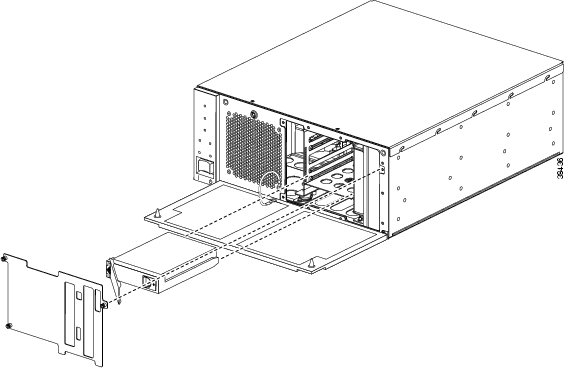
Figure 5-1 provides an example diagram of removing and replacing a hard disk drive from a
Netra t 1120/1125 chassis.Figure 5-1 Removing and Replacing a Hard Disk Drive
Removing a Hard Disk Drive
The procedures for removing a hard disk drive are found in the following sections:
•
•
•
Caution
Removing a Hard Disk Drive from a Netra t 100/105 Chassis
Perform the following steps to remove a hard disk drive from a Netra t 100/105 chassis:
Step 1
Step 2
Step 3
Step 4
Step 5
Step 6
Caution
Step 7
Step 8
Step 9
Step 10
Step 11
Step 12
Step 13
Removing a Hard Disk Drive from a Netra t 1120/1125 Chassis
Perform the following steps to remove a hard disk drive from a Netra t 1120/1125 chassis:
Step 1
Caution
Step 2
Caution
a.
b.
c.
Caution
Step 3
Step 4
Step 5
Step 6
Step 7
Step 8
Step 9
Removing a Hard Disk Drive from a Netra t 1400/1405 Chassis
Perform the following steps to remove a hard disk drive from a Netra t 1400/1405 chassis:
Step 1
Caution
a.
b.
c.
Caution
Step 2
Caution
Step 3
Step 4
Step 5
Step 6
Step 7
Step 8
Installing a Hard Disk Drive
The procedures for installing a hard disk drive are found in the following sections:
•
•
•
Caution
Installing a Hard Disk Drive in a Netra t 100/105 Chassis
Perform the following steps to install a hard disk drive in a Netra t 100/105 chassis:
Step 1
Step 2
Step 3
Step 4
Step 5
Step 6
Step 7
Step 8
Step 9
Step 10
Installing a Hard Disk Drive in a Netra t 1120/1125 Chassis
Perform the following steps to install a hard disk drive in a Netra t 1120/1125 chassis:
Step 1
Step 2
Step 3
Step 4
Step 5
Step 6
Step 7
a.
Note
b.
Step 8
Step 9
Installing a Hard Disk Drive in a Netra t 1400/1405 Chassis
Perform the following steps to install a hard disk drive in a Netra t 1400/1405 chassis:
Step 1
Step 2
Step 3
Step 4
Step 5
Step 6
a.
Note
b.
Step 7
Step 8
Upgrading Processors
Each of the server platforms requires the user of 440 MHz processors. The number of 440 MHz processors required in each server platform is as follows:
•
•
•
Depending on the number and speed of the processors in your host, you might have to replace your processor or add additional processors. The following sections contain procedures that describe how to remove and replace or add processors:
•
Note
Caution
Installing 440 MHz Processors
To install 440 MHz processors, follow the documentation that shipped with your processors. Typically the following documents are included:
•
•
p/n 802-3233-19
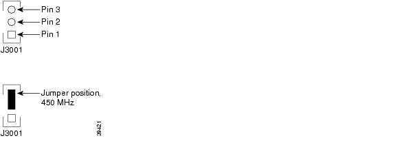
Note
Figure 5-2 Jumper Position for 450 MHz Processors
Removing a CPU Module
The procedures for removing a CPU module are found in the following sections:
•
•
Caution
Removing a CPU Module from a Netra t 1120/1125 Chassis
Perform the following steps to remove a CPU module from a Netra t 1120/1125 chassis:
Step 1
Step 2
Step 3
Caution
a.
b.
c.
Step 4
Step 5
Step 6
Removing a CPU Module from a Netra t 1400/1405 Chassis
Perform the following steps to remove a CPU module from a Netra t 1400/1405 chassis:
Step 1
Step 2
Step 3
Caution
a.
b.
c.
Step 4
Step 5
Step 6
Replacing a CPU Module
The procedures for replacing a CPU module are found in the following sections:
•
•
Caution
Replacing a CPU Module in a Netra t 1120/1125 Chassis
Perform the following steps to install a hard disk drive in a Netra t 1120/1125 chassis:
Step 1
Step 2
Step 3
Step 4
Step 5
Step 6
a.
b.
Step 7
Step 8
Step 9
Replacing a CPU Module in a Netra t 1400/1405 Chassis
Perform the following steps to install a hard disk drive in a Netra t 1400/1405 chassis:
Step 1
Step 2
Step 3
Step 4
Step 5
Step 6
a.
b.
Step 7
Step 8
Step 9
Upgrading Memory
The minimum amount of memory required in each server platform is as follows:
•
•
•
If you do not have enough memory, you must add additional memory modules of the following types:
•
•
•
The following sections contain procedures that describe how add additional memory:
Caution
Caution
Caution
Tip
Removing a Memory Module
The procedures for removing memory modules are found in the following sections:
•
•
•
Caution
Removing a Memory Board from a Netra t 100/105 Chassis
Perform the following steps to remove a memory board from a Netra t 100/105 chassis:
Step 1
Step 2
Step 3
Step 4
Step 5
Step 6
Step 7
Step 8
Step 9
Step 10
Removing a SIMM from a Netra t 1120/1125 Chassis
Perform the following steps to remove a memory board from a Netra t 1120/1125 chassis:
Caution
Step 1
Step 2
Step 3
Step 4
Caution
a.
b.
c.
d.
e.
f.
g.
h.
i.
j.
k.
l.
m.
Step 5
Step 6
Step 7
Caution
Step 8
Step 9
Removing a DIMM from a Netra t 1400/1405 Chassis
Perform the following steps to remove a memory board from a Netra t 1400/1405 chassis:
Caution
Step 1
Step 2
Step 3
Step 4
Step 5
Caution
Step 6
Step 7
Replacing a Memory Module
The procedures for removing memory modules are found in the following sections:
•
•
•
Caution
Replacing a Memory Board in a Netra t 100/105 Chassis
There is only one installation location for memory in the Netra t 100/105s. There are three sizes of memory available:
•
•
•
Note
Perform the following steps to replace a memory board in a Netra t 100/105 chassis:
Step 1
Step 2
Step 3
Step 4
Step 5
Step 6
Caution
Step 7
Step 8
Step 9
Step 10
Step 11
Step 12
Step 13
Replacing a SIMM in a Netra t 1120/1125 Chassis
Table 5-1 identifies SIMM installation locations in the Netra t 1120/1125s.
Table 5-1 SIMM Bank and Bank Quads
0
U0701, U0702, U0703, and U0704
1
U0801, U0802, U0803, and U0804
2
U0901, U0902, U0903, and U0904
3
U1001, U1002, U1003, and U1004
Perform the following steps to replace a SIMM in a Netra t 1120/1125 chassis:
Step 1
Step 2
Note
Caution
Step 3
Step 4
Step 5
Caution
Note
Step 6
a.
b.
c.
d.
e.
f.
g.
h.
i.
j.
k.
l.
m.
Step 7
Step 8
Step 9
Replacing a DIMM in a Netra t 1400/1405 Chassis
Table 5-2 identifies DIMM installation locations in the Netra t 1400/1405s.
Perform the following steps to replace a DIMM in a Netra t 1400/1405 chassis:
Step 1
Step 2
Note
Caution
Step 3
Step 4
Step 5
Note
Step 6
Step 7
Step 8
Verifying The Hardware Installation
After installing new hardware components, you can run a diagnostic program to ensure the system recognizes your components.
To run the diagnostic program:
Step 1
setenv auto-boot? falsesetenv diag-switch? trueThis disables automatic booting and runs a diagnostic program.
Step 2
Details about the system components, including hard drives, memory, and processors, appear on the screen. If you do not see the components you recently installed, you must perform troubleshooting steps to determine the problem. Contact the Cisco TAC for assistance in troubleshooting. See the "Obtaining Technical Assistance" section on page xviii for more information.
Step 3
setenv auto-boot? truesetenv diag-switch? falseStep 4
Where to Go Next
This completes upgrading your hardware. Return to the appropriate upgrade procedure for your solution for the next step in your upgrade.
![]()
![]()
![]()
![]()
![]()
![]()
![]()
![]()
Posted: Wed Oct 20 13:24:24 PDT 2004
All contents are Copyright © 1992--2004 Cisco Systems, Inc. All rights reserved.
Important Notices and Privacy Statement.