|
|

Table Of Contents
Understanding the Cisco Mobile Wireless Network
Public Safety Wireless Network Example
Data Flow to and from the Home Network
Overview
The Cisco wireless mobile interface Card (WMIC) provides wireless connectivity for the Cisco 3200 Series wireless and mobile router. WMICs operate in the 2.4-GHz (license-free) or 4.9-GHz (public safety) bands and conform to the 802.11 standards.
For additional information, see the "Roles and the Associations of Wireless Devices" document at: http://www.cisco.com/en/US/products/hw/routers/ps272/prod_configuration_basics09186a008073f6b7.html
Understanding the Cisco Mobile Wireless Network
This section provides descriptions of basic wireless network configurations.
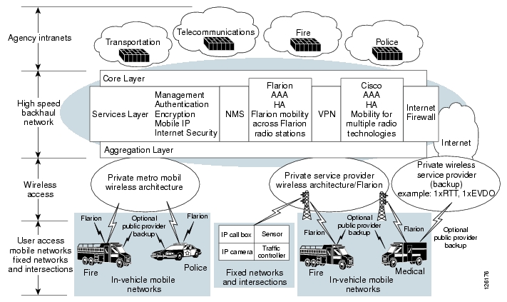
Public Safety Wireless Network Example
A Cisco Mobile Wireless Network provides wireless network services to multiple safety departments, such as police, fire, emergency medical services, and other public safety agencies.
The wireless technologies used in the Cisco Metropolitan Mobile Network include broadband wireless connectivity, providing high speed access for bandwidth-intensive applications, such as in-car video. To supplement the coverage areas where wireless network access is not provided, cellular service, such as code division multiple access (CDMA) 1xEVDO, can be used to fill gaps in connections and provide backup wireless connectivity.
The Cisco 3200 Series routers serve as aggregation devices in public safety vehicles and communicate with the broadband wireless infrastructure as well as aggregation devices at traffic intersections. This extends the existing agency IP network out to traffic intersections. A networked traffic intersection enables connections back to the agency network, providing central coordination of traffic signals and transferring streaming video to and from IP cameras.
Figure 1-1 Example of the Network Architecture for Emergency Services
Intersection Example
In the Cisco Metro Mobile Architecture, each intersection is equipped with a Cisco 3200 Series router. An intersections is classified as either a primary intersection or a secondary intersection. A primary intersection funnels all traffic from surrounding secondary intersections through the backhaul to the core network. Within each cluster of primary and secondary intersections, typically there are two primary intersections for diversity.
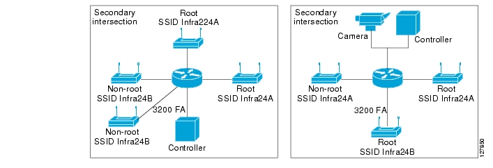
The Cisco 3200 Series routers at the secondary intersections are connected to all of the network devices at that intersection, such as a traffic controller and a video camera. In Figure 1-2, there are three bridges on the secondary intersections (integrated into the Cisco 3200 Series router). Two of the bridges are point-to-point links to other primary or secondary intersections in the local service area, and one is a root device serving mobile units in the area.
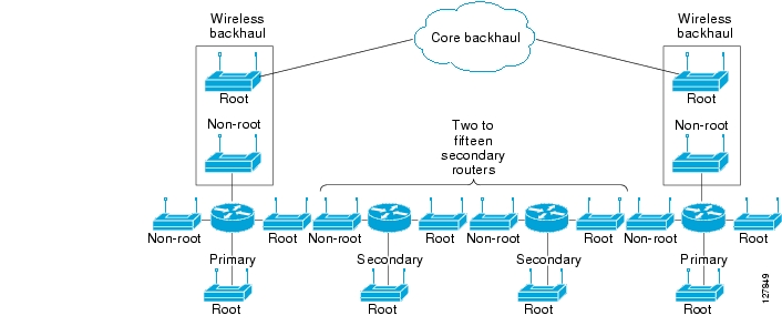
Figure 1-2 Intersection to Backhaul Example
The Cisco 3200 Series routers at the primary intersections connect to the wireless backhaul by using an integrated bridge. Figure 1-3 shows the intersection layout.
Figure 1-3 Primary Intersection and Secondary Intersection Layouts
This configuration supports a long chain of primary and secondary intersections. The number of secondary intersections allowed between two primary intersections depends on factors such as line-of-sight and bandwidth.
All secondary and primary intersections run an Interior Gateway Protocol (IGP), so the path to every primary and secondary intersection is advertised throughout the network. Applications, such as video and data communications, can be accessed from anywhere in the network. When a packet from a mobile unit arrives, the packet is forwarded to either end of the primary intersections in its cluster. The packet takes the shortest path based on routing metrics.
To extend IP networks to various parts of the community and achieve sufficient bandwidth for the required number of users and required applications, the Cisco Metro Mobile Network can use different methods of backhaul, including a fiber network, leased lines, or broadband wireless bridging. Each primary intersection has either a wireless or wired connection back to a nearby building.
Vehicle Network Example
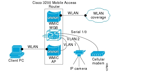
A Cisco 3200 Series router installed in a mobile unit allows the client devices in and around the vehicle to stay connected while roaming. WMICs in vehicle-mounted Cisco 3200 Series routers are configured as access points to provide connectivity for 802.11b/g and 4.9-GHz wireless clients. Ethernet interfaces are be used to connect any in-vehicle wired clients, such as a laptop or a camera, to the network.
Another WMIC is configured as workgroup bridge for connectivity to a root device at an intersection. This allows it to transparently associate and authenticate through each root device in the architecture as the vehicle moves about.
Serial interfaces provide connectivity to wireless WAN modems that connect to cellular networks that use either CDMA or general packet radio service (GPRS). Wireless 802.11 connections are the preferred service because they offer the most bandwidth; however, since a wireless connection is not always available, cellular technology provides a backup link.
Figure 1-4 shows an example of the devices that can connect to the Cisco 3200 Series router in each mobile unit.
Figure 1-4 Example Mobile Unit Configuration
Data Path Example
The wired and wireless devices in the mobile unit are not aware that they are mobile. When they must communicate with another node in the network, they send the request to their default gateway, the Cisco 3200 Series router. The Cisco 3200 Series router builds a modem over IP (MoIP) tunnel to its home agent, encapsulating the data packets.
When the Cisco 3200 Series router sends traffic over the wireless link, the MoIP tunnel goes from the local foreign agent to a local aggregation point and through the backhaul link to the home agent where the encapsulation is removed from the data packets.
If the mobile router is out of the wireless coverage area and a cellular technology is used to complete the connection to the home agent, the Mobile IP tunnel is built across the service provider network and into the home agent. The mobile router chooses a wireless link, depending on the following factors:
•
Which link is up (and available for use)
•
•
•
Regardless of which link is up, all traffic from the mobile devices travel through the MoIP tunnel to the home agent, where it is routed to its destination.
Call Setup Process
This section describes the processes of call setup and data flow as the Cisco 3200 Series router moves into the vicinity of the hot spot and exchanges data packets.
1.
2.
3.
4.
5.
6.
7.
8.
9.
10.
Data Flow to and from the Home Network
The Cisco 3200 Series router is registered to its home agent using the foreign agent CoA. If any devices attached to the Cisco 3200 Series router must communicate with nodes on the home network, they send the data to the Cisco 3200 Series router.
1.
2.
3.
4.
5.
Data intended for the Cisco 3200 Series router mobile network from anywhere in the network must be sent through the VPN gateway for encryption, and then sent to the home agent for encapsulation.
1.
2.
If the mobile vehicle is not in the vicinity of a wireless LAN hot spot, the vehicle uses a backup wireless service, such as cellular, to deliver the data. In this case, the Cisco 3200 Series router acquires a dynamic collocated care-of address (CCoA) address from the service provider network and the Cisco 3200 Series router registers with the home agent.
The registration process is similar to the process for CoA registration. The encapsulation and encryption process is also similar.
Features
The WMIC running Cisco IOS offers these software features:
•
•
•
•
•
•
•
•
•
•
•
•
•
•
•
Note
The key differences between the 2.4-GHz WMIC and the 4.9-GHz WMIC are shown in Table 1-1.
Table 1-1 Differences Between the 2.4-GHz WMIC and the 4.9-GHz WMIC
Cisco IOS image release
12.3(8) JK
12.3.(2) JK
Cookie and banner
C3201
C3202
Frequency
2.4 GHz
4.9 GHz
Data rates
802.11b data rates are 1 Mbps, 2 Mbps, 5.5 Mbps, and 11 Mbps.
802.11g data rates are 1 Mbps, 2 Mbps, 5.5 Mbps, 6 Mbps, 9 Mbps, 11 Mbps, 12 Mbps, 18 Mbps, 24 Mbps, 36 Mbps, 48 Mbps, and 54 Mbps
20MHz baseband data rates are 6 Mbps, 9 Mbps, 12 Mbps, 18 Mbps, 24 Mbps, 36 Mbps, 48 Mbps, and 54 Mbps
10MHz baseband data rates are 3 Mbps, 4.5 Mbps, 6 Mbps, 9 Mbps, 12 Mbps, 18 Mbps, 24 Mbps, and 27 Mbps.
5MHz baseband data rates are 1.5 Mbps, 2.25 Mbps, 3 Mbps, 4.5 Mbps, 6 Mbps, 9 Mbps, 12 Mbps, and 13.5 Mbps
The dot11 interface speed command manages data rates and applies only to the 4.9-GHz WMIC. See "Configuring Radio Data Rates" in Chapter 3, "Configuring Radio Settings."
Power
Maximum orthogonal frequency-division multiplexing (OFDM) power level is 15 dBm (30 mW). This varies by country.
Maximum OFDM power level is 16 dBm (40 mW). U.S. only.
The dot11 interface power command is used to manage the power levels.
Concatenation
Supported
Not supported
World mode
Supported
Not supported
World mode is supported for the U.S., European, and Japanese regulatory domains; however, the choice of radio limits the available channels and transmit power. To use the workgroup bridge and non-root bridge in the U.S.and Europe, select the European SKU; to use them in the U.S. and Japan, select the Japanese SKU; to use them in the Japan and Europe, select the Japanese SKU.
Universal workgroup bridge mode
Supported
Not supported
Enables operation with non-Cisco Aironet access points.
Multiple client profile
Supported
Not supported
Support is enabled only when universal workgroup bridge mode is enabled.
Multiple basic SSIDs
Supported
Not supported
VLAN
16 unencrypted VLANs,
16 static key VLANs, or
16 dynamic key VLANs16 unencrypted VLANs,
1 static key VLANs, or
4 dynamic key VLANsWireless encryption/cipher suites
WEP-40, WEP-128, TKIP, CKIP, CMIC, and CKIP-CMIC, AES-CCM
WEP-40, WEP-128, TKIP, and AES-CCM
CKIP, CMIC and CKIP-CMIC are not part of 802.11 standard cipher suites.
Maximum number of stations with WEP
255
116
Maximum number of stations with TKIP
256
26
Maximum number of stations with AES-CCM
256
116
Channelization
Statically declared as defined by IEEE 802.11b/g.
Channel spacing selected by using the CLI.
Scanning enhancements for faster roaming
All Scanning Enhancements for Faster Roaming are available.
All Scanning Enhancements for Faster Roaming are available except "Use First Better Access Point."
•
•
•
•
•
•
•
•
CCXv4 features
Supported
Not supported
802.11e MMN QoS
Supported
Not supported
EAP-TLS, EAP-TTLS, EAP-FAST
EAP-TLS and EAP-FAST are supported on root and non-root devices.
EAP-TTLS is supported on root devices only.
Not supported
Simple Network Management Protocol (SNM)P MIB IDs
Supported
Supported for new values
The platform-dependent SNMP code was modified to return new values (entPhysicalVendorType, System OID, and Chassis ID).
Dot11 MIB parameters
Supported
The dot11 parameters are returned through the dot11 MIB interface.
Management Options
You can use the WMIC management system through the following interfaces:
•
•
![]()
![]()
![]()
![]()
![]()
![]()
![]()
![]()
Posted: Wed Feb 13 22:34:41 PST 2008
All contents are Copyright © 1992--2008 Cisco Systems, Inc. All rights reserved.
Important Notices and Privacy Statement.