|
|

Table Of Contents
Configuring a System Name and Prompt
Displaying the DNS Configuration
Configuring a Message-of-the-Day Login Banner
Protecting Access to Privileged EXEC Commands
Default Password and Privilege Level Configuration
Setting or Changing a Static Enable Password
Protecting Enable and Enable Secret Passwords with Encryption
Configuring Username and Password Pairs
Configuring Multiple Privilege Levels
Configuring and Enabling RADIUS
Controlling WMIC Access with RADIUS
Controlling WMIC Access with TACACS+
Configuring TACACS+ Login Authentication
Configuring TACACS+ Authorization for Privileged EXEC Access and Network Services
Displaying the TACACS+ Configuration
Configuring the WMIC for Local Authentication and Authorization
Configuring the WMIC for Secure Shell
Managing the System Time and Date
Understanding the System Clock
Understanding Network Time Protocol
Configuring Time and Date Manually
Administering the WMIC
This chapter describes how to administer the Cisco Wireless Mobile Interface (WMIC).
Configuring a System Name and Prompt
You configure the system name on the WMIC to identify it. A "greater than" symbol (>) is appended. The prompt is updated whenever the system name changes, unless you manually configure the prompt by using the prompt command in global configuration mode.
Note
For complete syntax and usage information for the commands used in this section, see the Cisco IOS Configuration Fundamentals Command Reference and the Cisco IOS IP and IP Routing Command Reference for Release 12.1.
Configuring a System Name
To manually configure a system name, follow these steps, beginning in privileged EXEC mode:
When you set the system name, it is also used as the system prompt.
To return to the default hostname, use the no hostname global configuration command.
Managing DNS
The DNS protocol controls the Domain Name System (DNS), a distributed database with which you can map hostnames to IP addresses. When you configure DNS on your WMIC, you can substitute the hostname for the IP address with all IP commands, such as ping, telnet, connect, and related Telnet support operations.
IP defines a hierarchical naming scheme that allows a device to be identified by its location or domain. Domain names are pieced together with periods (.) as the delimiting characters. For example, Cisco Systems is a commercial organization that is identified by a com domain name; its domain name is cisco.com.
To keep track of domain names, IP has defined the concept of a domain name server that holds a cache (or database) of names mapped to IP addresses. To map domain names to IP addresses, identify the hostnames, specify the name server that is present on your network, and enable the DNS.
Default DNS Configuration
Table 4-1 shows the default DNS configuration.
Table 4-1 Default DNS Configuration
DNS enable state
Disabled.
DNS default domain name
None configured.
DNS servers
No name server addresses are configured.
Setting Up DNS
To set up your WMIC to use the DNS, follow these steps, beginning in privileged EXEC mode:
If you use the WMIC IP address as its hostname, the IP address is used and no DNS query occurs. If you configure a hostname that contains no periods (.), a period followed by the default domain name is appended to the hostname before the DNS query is made to map the name to an IP address.
The default domain name is the value set by the ip domain-name global configuration command. If there is a period (.) in the hostname, the Cisco IOS software looks up the IP address without appending any default domain name to the hostname.
To remove a domain name, use the no ip domain-name name command in global configuration mode. To remove a name server address, use the no ip name-server server-address command in global configuration mode. To disable DNS on the WMIC, use the no ip domain-lookup command in global configuration mode.
Displaying the DNS Configuration
To display the DNS configuration information, use the show running-config command in privileged EXEC command.
Creating a Banner
You can configure a message-of-the-day (MOTD) and a login banner. The MOTD banner appears on all connected terminals at login and is useful for sending messages that affect all network users (such as impending system shutdowns).
The login banner also appears on all connected terminals. It appears after the MOTD banner and before the login prompts.
Note
Default Banner Configuration
The MOTD and login banners are not configured.
Configuring a Message-of-the-Day Login Banner
You can create a single- or multiple-line message banner that appears on the screen when someone logs in to the WMIC.
To configure a MOTD login banner, follow these steps, beginning in privileged EXEC mode:
To delete the MOTD banner, use the no banner motd global configuration command.
This example shows how to configure a MOTD banner for the WMIC by using the pound sign (#) as the beginning and ending delimiter:
bridge(config)# banner motd #This is a secure site. Only authorized users are allowed.For access, contact technical support.#bridge(config)#This example shows the banner displayed from the previous configuration:
Unix> telnet 172.2.5.4Trying 172.2.5.4...Connected to 172.2.5.4.Escape character is '^]'.This is a secure site. Only authorized users are allowed.For access, contact technical support.User Access VerificationPassword:Configuring a Login Banner
You can configure a login banner to appear on all connected terminals. This banner appears after the MOTD banner and before the login prompt.
To configure a login banner, follow these steps, beginning in privileged EXEC mode:
To delete the login banner, use the no banner login global configuration command.
This example shows how to configure a login banner for the WMIC using the dollar sign ($) symbol as the beginning and ending delimiter:
bridge(config)# banner login $Access for authorized users only. Please enter your username and password.$bridge(config)#Protecting Access to Privileged EXEC Commands
A simple way of controlling terminal access in your network is to use passwords and assign privilege levels. Password protection restricts access to a network or network device. Privilege levels define what commands users can issue after they have logged into a network device.
Note
This section describes how to control access to the configuration file and privileged EXEC commands.
Default Password and Privilege Level Configuration
Table 4-2 shows the default password and privilege level configuration.
Setting or Changing a Static Enable Password
The enable password controls access to the privileged EXEC mode.
Note
To set or change a static enable password, follow these steps, beginning in privileged EXEC mode:
This example shows how to change the enable password to l1u2c3k4y5. The password is not encrypted and provides access to level 15 (traditional privileged EXEC mode access).
bridge(config)# enable password l1u2c3k4y5Protecting Enable and Enable Secret Passwords with Encryption
To provide an additional layer of security, particularly for passwords that cross the network or that are stored on a Trivial File Transfer Protocol (TFTP) server, you can use either the enable password or the enable secret command. Both commands accomplish the same thing; that is, you can establish an encrypted password that users must enter to access privileged EXEC mode (the default) or any privilege level you specify.
We recommend that you use the enable secret command because it uses an improved encryption algorithm.
If you configure the enable secret command, it takes precedence over the enable password command; the two commands cannot be in effect simultaneously.
To configure encryption for enable and enable secret passwords, follow these steps, beginning in privileged EXEC mode:
If both the enable and enable secret passwords are defined, users must enter the enable secret password.
Use the level keyword to define a password for a specific privilege level. After you specify the level and set a password, give the password only to users who need to have access at this level. To specify commands accessible at various levels, use the privilege level command in global configuration mode. For more information, see the "Configuring Multiple Privilege Levels" section.
If you enable password encryption, it applies to all passwords, including username passwords, authentication key passwords, the privileged command password, and console and virtual terminal line passwords.
To remove a password and level, use the no enable password [level level] or no enable secret [level level] command in global configuration mode. To disable password encryption, use the no service password-encryption command in global configuration mode.
This example shows how to configure the encrypted password $1$FaD0$Xyti5Rkls3LoyxzS8 for privilege level 2:
bridge(config)# enable secret level 2 5 $1$FaD0$Xyti5Rkls3LoyxzS8Configuring Username and Password Pairs
You can configure username and password pairs, which are locally stored on the WMIC. These pairs are assigned to lines or interfaces, and they authenticate each user before that user can access the WMIC. If you have defined privilege levels, you can also assign a specific privilege level (with associated rights and privileges) to each username and password pair.
To establish a username-based authentication system that requests a login username and a password, follow these steps, beginning in privileged EXEC mode:
To disable username authentication for a specific user, use the no username name command in global configuration mode.
To disable password checking and allow connections without a password, use the no login command in line configuration mode.
Note
Configuring Multiple Privilege Levels
By default, the Cisco IOS software has two modes of password security: user EXEC and privileged EXEC. You can configure up to 16 hierarchical levels of commands for each mode. By configuring multiple passwords, you can allow different sets of users to have access to specified commands.
For example, if you want many users to have access to the clear line command, you can assign it level 2 security and distribute the level 2 password fairly widely. But if you want fewer users to have access to the configure command, you can assign it level 3 security and distribute that password to a smaller group of users.
Setting the Privilege Level for a Command
To set the privilege level for a command mode, follow these steps, beginning in privileged EXEC mode:
When you set a command to a privilege level, all commands whose syntax is a subset of that command are also set to that level. For example, if you set the show ip route command to level 15, the show commands and show ip commands are automatically set to privilege level 15 unless you set them individually to different levels.
To return to the default privilege for a given command, use the no privilege mode level level command command in global configuration mode.
This example shows how to set the configure command to privilege level 14 and define SecretPswd14 as the password that users must enter to use level 14 commands:
bridge(config)# privilege exec level 14 configurebridge(config)# enable password level 14 SecretPswd14Logging Into and Exiting a Privilege Level
To log in to a specified privilege level and to exit to a specified privilege level, follow these steps, beginning in privileged EXEC mode:
Protecting the Wireless LAN
Configure security settings to prevent unauthorized access to your network. Because it is a radio device, the WMIC can communicate beyond the physical boundaries of your building. You can apply advanced security features such as the following:
•
•
•
Using VLANs
Assign SSIDs to the VLANs on the wireless LAN. If you do not use VLANs on the wireless LAN, the security options that can be assigned to SSIDs are limited, because encryption settings and authentication types are linked. Without VLANs, encryption settings (WEP and ciphers) are applied to an interface, and no more than one encryption setting can be used on each interface.
For example, if an SSID with static WEP is created with VLANs disabled, an additional SSID with Wi-Fi Protected Access (WPA) authentication cannot be created because of the different encryption settings. If a security setting for an SSID conflicts with another SSID, delete one or more SSIDs to eliminate the conflict.
Express Security Types
Table 4-3 describes the four security types that you can assign to an SSID.
Security Configuration Examples
This section contains these configuration examples:
•
No Security SSID Example
This example shows part of the configuration for creating an SSID called no_security_ssid, including the SSID in the beacon, assigning it to VLAN 10, and selecting VLAN 10 as the native VLAN (as it applies to the 2.4-GHz ([802.11b/g]) WMIC):
interface Dot11Radio0no ip addressno ip route-cache!ssid no_security-ssidvlan 10authentication openguest-mode!concatenationspeed basic-1.0 basic-2.0 basic-5.5 6.0 9.0 basic-11.0 12.0 18.0 24.0 36.0 48.0 54.0rts threshold 4000station-role rootinfrastructure-clientbridge-group 1!interface Dot11Radio0.10encapsulation dot1Q 10no ip route-cachebridge-group 10bridge-group 10 spanning-disabled!interface FastEthernet0no ip addressno ip route-cacheduplex autospeed autobridge-group 1!interface FastEthernet0.10encapsulation dot1Q 10no ip addressno ip route-cacheduplex autospeed autobridge-group 1As it applies to the 4.9-GHz WMIC:
hostname root!username Cisco password 7 02250D480809ip subnet-zero!no aaa new-model!bridge irb!interface Dot11Radio0no ip addressno ip route-cache!ssid testauthentication openinfrastructure-ssid!spacing 5 channel 4942speed basic-1.5 2.25 basic-3.0 4.5 basic-6.0 9.0 12.0 13.5power local 10station-role rootinfrastructure-clientbridge-group 1bridge-group 1 spanning-disabled!interface FastEthernet0no ip addressno ip route-cacheduplex autospeed autobridge-group 1bridge-group 1 spanning-disabled!interface BVI1ip address 192.1.1.2 255.255.255.0no ip route-cache!ip http serverno ip http secure-serverip http help-path http://www.cisco.com/warp/public/779/smbiz/prodconfig/help/eagip radius source-interface BVI1logging snmp-trap emergencieslogging snmp-trap alertslogging snmp-trap criticallogging snmp-trap errorslogging snmp-trap warningsbridge 1 route ip!!!line con 0exec-timeout 0 0transport preferred alltransport output allline vty 0 4login localtransport preferred alltransport input alltransport output allline vty 5 15logintransport preferred alltransport input alltransport output all!endStatic WEP Security Example
This example shows part of the configuration for creating an SSID called static_wep_ssid, excluding the SSID from the beacon, assigning the SSID to VLAN 20, selecting 3 as the key slot, and entering a 128-bit key:
interface Dot11Radio0no ip addressno ip route-cache!encryption vlan 20 key 3 size 128bit 7 4E78330C1A841439656A9323F25A transmit-keyencryption vlan 20 mode wep mandatory!ssid static_wep_ssidvlan 20authentication open!concatenationspeed basic-1.0 basic-2.0 basic-5.5 6.0 9.0 basic-11.0 12.0 18.0 24.0 36.0 48.0 54.0rts threshold 4000station-role rootinfrastructure-clientbridge-group 1!interface Dot11Radio0.20encapsulation dot1Q 20no ip route-cachebridge-group 20bridge-group 20 spanning-disabled!interface FastEthernet0no ip addressno ip route-cacheduplex autospeed autobridge-group 1!interface FastEthernet0.20encapsulation dot1Q 20no ip route-cachebridge-group 20bridge-group 20 spanning-disabledEAP Authentication Security Example
This example shows part of the configuration for creating an SSID called eap_ssid, excluding the SSID from the beacon, and assigning the SSID to VLAN 30:
interface Dot11Radio0no ip addressno ip route-cache!encryption vlan 30 mode wep mandatory!ssid eap_ssidvlan 30authentication open eap eap_methodsauthentication network-eap eap_methods!speed basic-1.0 basic-2.0 basic-5.5 basic-11.0rts threshold 2312station-role rootbridge-group 1bridge-group 1 subscriber-loop-controlbridge-group 1 block-unknown-sourceno bridge-group 1 source-learningno bridge-group 1 unicast-floodingbridge-group 1 spanning-disabled!interface Dot11Radio0.30encapsulation dot1Q 30no ip route-cachebridge-group 30bridge-group 30 subscriber-loop-controlbridge-group 30 block-unknown-sourceno bridge-group 30 source-learningno bridge-group 30 unicast-floodingbridge-group 30 spanning-disabled!interface FastEthernet0mtu 1500no ip addressip mtu 1564no ip route-cacheduplex autospeed autobridge-group 1no bridge-group 1 source-learningbridge-group 1 spanning-disabled!interface FastEthernet0.30mtu 1500encapsulation dot1Q 30no ip route-cachebridge-group 30no bridge-group 30 source-learningbridge-group 30 spanning-disabled!WPA Security Example
This example shows part of the configuration for creating an SSID called wpa_ssid, excluding the SSID from the beacon, and assigning the SSID to VLAN 40:
aaa new-model!aaa group server radius rad_eapserver 10.91.104.92 auth-port 1645 acct-port 1646!aaa group server radius rad_mac!aaa group server radius rad_acct!aaa group server radius rad_admin!aaa group server tacacs+ tac_admin!aaa group server radius rad_pmip!aaa group server radius dummy!aaa authentication login eap_methods group rad_eapaaa authentication login mac_methods localaaa authorization exec default localaaa authorization ipmobile default group rad_pmipaaa accounting network acct_methods start-stop group rad_acctaaa session-id common!!bridge irb!!interface Dot11Radio0no ip addressno ip route-cache!encryption vlan 40 mode ciphers tkip!ssid wpa_ssidvlan 40authentication open eap eap_methodsauthentication network-eap eap_methodsauthentication key-management wpa!concatenationspeed basic-1.0 basic-2.0 basic-5.5 6.0 9.0 basic-11.0 12.0 18.0 24.0 36.0 48 54.0rts threshold 4000station-role rootinfrastructure-clientbridge-group 1!interface Dot11Radio0.40encapsulation dot1Q 40no ip route-cachebridge-group 40!interface FastEthernet0no ip addressno ip route-cacheduplex autospeed autobridge-group 1!interface FastEthernet0.40encapsulation dot1Q 40no ip route-cachebridge-group 40!ip http serverip http help-path http://www.cisco.com/warp/public/779/smbiz/prodconfig/help/eag/122-15.JA/1100ip radius source-interface BVI1radius-server attribute 32 include-in-access-req format%hradius-server host 10.91.104.92 auth-port 1645 acct-port 1646 key 7 135445415F59radius-server authorization permit missing Service-Typeradius-server vsa send accountingbridge 1 route ip!line con 0line vty 5 15!endConfiguring and Enabling RADIUS
This section describes how to configure and enable Remote Authentication Dial-In User Service (RADIUS).
Understanding RADIUS
RADIUS is a distributed client/server system that secures networks against unauthorized access. RADIUS clients run on supported Cisco devices and send authentication requests to a central RADIUS server that contains all user authentication and network service access information. The RADIUS host is normally a multiuser system running RADIUS server software from Cisco, Livingston, Merit, Microsoft, or another software provider. For more information, see the RADIUS server documentation.
Use RADIUS in these network environments:
•
•
•
•
RADIUS is not suitable for these network situations:
•
•
•
RADIUS Operation
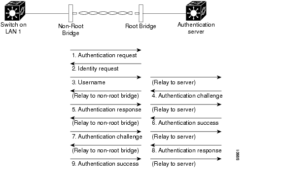
When a non-root bridge attempts to authenticate to a bridge whose access is controlled by a RADIUS server, authentication to the network occurs in the steps shown in Figure 4-1.
Figure 4-1 Sequence for EAP Authentication
In Figure 4-1, a non-root bridge and a RADIUS server on the wired LAN use 802.1x and EAP to perform a mutual authentication through the root device. The RADIUS server sends an authentication challenge to the non-root bridge. The non-root bridge uses a one-way encryption of the user-supplied password to generate a response to the challenge and sends that response to the RADIUS server. Using information from its user database, the RADIUS server creates its own response and compares that to the response from the non-root bridge. When the RADIUS server authenticates the non-root bridge, the process repeats in reverse, and the non-root bridge authenticates the RADIUS server.
When mutual authentication is complete, the RADIUS server and the non-root bridge determine a WEP key that is unique to the non-root bridge and that provides the non-root bridge with the appropriate level of network access, thereby approximating the level of security in a wired switched segment to an individual desktop. The non-root bridge loads this key and prepares to use it for the logon session.
During the logon session, the RADIUS server encrypts and sends the WEP key, called a session key, over the wired LAN to the root device. The root device encrypts its broadcast key with the session key and sends the encrypted broadcast key to the non-root bridge, which uses the session key to decrypt it. The non-root bridge and the root device activate WEP and use the session and broadcast WEP keys for all communications during the remainder of the session.
There is more than one type of EAP authentication, but the root device behaves the same way for each type: it relays authentication messages from the non-root bridge to the RADIUS server and from the RADIUS server to the non-root bridge. See the "Assigning Authentication Types to an SSID" section on page 9-15 for instructions on setting up authentication using a RADIUS server.
Controlling WMIC Access with RADIUS
This section describes how to control administrator access to the WMIC using RADIUS.
RADIUS provides detailed accounting information and flexible administrative control over authentication and authorization processes. RADIUS is facilitated through AAA and can be enabled only through authentication, authorization, and accounting (AAA) commands. RADIUS and AAA are disabled by default.
At a minimum, the host or hosts that run the RADIUS server software must be identified and the method lists for RADIUS authentication must be defined. Optionally, method lists for RADIUS authorization and accounting can be defined.
A method list defines the sequence and methods to be used to authenticate, to authorize, or to keep accounts on a non-root bridge. Method lists are used to designate one or more security protocols to be used, thus ensuring a backup system if the initial method fails. The software uses the first method listed to authenticate, to authorize, or to keep accounts on non-root bridges; if that method does not respond, the software selects the next method in the list. This process continues until there is successful communication with a listed method or the method list is exhausted.
You must have access to and should configure a RADIUS server before you configure RADIUS features.
These sections describe RADIUS configuration:
•
•
•
•
•
•
•
Note
Identifying the RADIUS Server Host
Access point-to-RADIUS-server communication involves several components:
•
•
•
•
•
•
RADIUS security servers are identified by their hostname or IP address, hostname and specific User Datagram Protocol (UDP) port numbers, or IP address and specific UDP port numbers. The combination of the IP address and the UDP port number creates a unique identifier allowing different ports to be individually defined as RADIUS hosts providing a specific AAA service. This unique identifier enables RADIUS requests to be sent to multiple UDP ports on a server at the same IP address.
If two different host entries on the same RADIUS server are configured for the same service—such as accounting—the second host entry configured acts as a failover backup to the first one. Using this example, if the first host entry fails to provide accounting services, the bridge tries the second host entry configured on the same device for accounting services. (The RADIUS host entries are tried in the order that they are configured.)
A RADIUS server and the bridge use a shared secret text string to encrypt passwords and exchange responses. To configure RADIUS to use the AAA security commands, you must specify the host that is running the RADIUS server daemon and a secret text (key) string that it shares with the bridge.
The timeout, retransmission, and encryption key values can be configured globally per server for all RADIUS servers or in some combination of global and per-server settings. To apply these settings globally to all RADIUS servers communicating with the bridge, use the three unique global configuration commands: radius-server timeout, radius-server retransmit, and radius-server key. To apply these values on a specific RADIUS server, use the radius-server host command in global configuration mode.
Note
You can configure the bridge to use AAA server groups to group existing server hosts for authentication. For more information, see the "Defining AAA Server Groups" section.
To configure per-server RADIUS server communication, follow these required steps, beginning in privileged EXEC mode:
To remove the specified RADIUS server, use the no radius-server host hostname | ip-address command in global configuration mode.
This example shows how to configure one RADIUS server for authentication and another for accounting:
bridge(config)# radius-server host 172.29.36.49 auth-port 1612 key rad1bridge(config)# radius-server host 172.20.36.50 acct-port 1618 key rad2This example shows how to configure host1 as the RADIUS server using the default ports for both authentication and accounting:
bridge(config)# radius-server host host1Configuring RADIUS Login Authentication
To configure AAA authentication, define a named list of authentication methods and apply that list to various interfaces. The method list defines the types of authentication to be performed and the sequence in which they are performed; the list must be applied to a specific interface before any of the defined authentication methods are performed. The only exception is the default method list (which is named default). The default method list is automatically applied to all interfaces except those for which a named method list is explicitly defined.
A method list describes the sequence and authentication methods to be queried to authenticate a user (in this case, a non-root bridge). Designate one or more security protocols to be used for authentication, to ensure a backup system for authentication if the initial method fails. The software uses the first method listed to authenticate users; if that method fails to respond, the software selects the next authentication method in the method list. This process continues until there is successful communication with a listed authentication method or until all defined methods are exhausted. If authentication fails at any point in this cycle; that is, if the security server or local username database responds by denying the user access—the authentication process stops, and no further authentication methods are attempted.
To configure login authentication, follow these required steps, beginning in privileged EXEC mode:
Step 1
configure terminal
Enters global configuration mode.
Step 2
aaa new-model
Enables AAA.
Step 3
aaa authentication login {default | list-name} method1 [method2...]
Creates a login authentication method list.
•
•
Select one of these methods:
•
•
•
Step 4
line [console | tty | vty] line-number [ending-line-number]
Enters line configuration mode, and configures the lines to apply the authentication list.
Step 5
login authentication {default | list-name}
Applies the authentication list to a line or set of lines.
•
•
Step 6
radius-server attribute 32 include-in-access-req format %h
Configures the device to send its system name in the NAS_ID attribute for authentication.
Step 7
end
Returns to privileged EXEC mode.
Step 8
show running-config
Verifies your entries.
Step 9
copy running-config startup-config
(Optional) Saves your entries in the configuration file.
To disable AAA, use the no aaa new-model command in global configuration mode. To disable AAA authentication, use the no aaa authentication login {default | list-name} method1 [method2...] command in global configuration mode. To disable RADIUS authentication for logins or to return to the default value, use the no login authentication {default | list-name} command in line configuration mode.
Defining AAA Server Groups
Configure the bridge to use AAA server groups to group existing server hosts for authentication. Select a subset of the configured server hosts, and use them for a particular service. The server group is used with a global server-host list, which lists the IP addresses of the selected server hosts.
Server groups also can include multiple host entries for the same server if each entry has a unique identifier (the combination of the IP address and UDP port number), allowing different ports to be individually defined as RADIUS hosts providing a specific AAA service. If you configure two different host entries on the same RADIUS server for the same service (such as accounting), the second configured host entry acts as a failover backup to the first one.
Use the server group server configuration command to associate a particular server with a defined group server. To identify the server by its IP address or to identify multiple host instances or entries, use the optional auth-port and acct-port keywords.
To define the AAA server group and associate a particular RADIUS server with it, follow these steps, beginning in privileged EXEC mode:
Step 1
configure terminal
Enters global configuration mode.
Step 2
aaa new-model
Enables AAA.
Step 3
radius-server host {hostname | ip-address} [auth-port port-number] [acct-port port-number] [timeout seconds] [retransmit retries] [key string]
Specifies the IP address or hostname of the remote RADIUS server host.
•
•
•
•
•
Note
To configure the bridge to recognize more than one host entry associated with a single IP address, enter this command as many times as necessary, making sure that each UDP port number is different. The bridge software searches for hosts in the order in which you specify them. Set the timeout, retransmit, and encryption key values to use with the specific RADIUS host.
Step 4
aaa group server radius group-name
Defines the AAA server-group with a group name.
This command puts the bridge in a server group configuration mode.
Step 5
server ip-address
Associates a particular RADIUS server with the defined server group. Repeat this step for each RADIUS server in the AAA server group.
Note
Step 6
end
Returns to privileged EXEC mode.
Step 7
show running-config
Verifies your entries.
Step 8
copy running-config startup-config
(Optional) Saves your entries in the configuration file.
Step 9
Enables RADIUS login authentication. See the "Configuring RADIUS Login Authentication" section.
To remove the specified RADIUS server, use the no radius-server host hostname | ip-address command in global configuration mode. To remove a server group from the configuration list, use the no aaa group server radius group-name command in global configuration mode. To remove the IP address of a RADIUS server, use the no server ip-address command in server group configuration mode.
In this example, the bridge is configured to recognize two different RADIUS group servers (group1 and group2). Group1 has two different host entries on the same RADIUS server configured for the same services. The second host entry acts as a failover backup to the first entry.
bridge(config)# aaa new-modelbridge(config)# radius-server host 172.20.0.1 auth-port 1000 acct-port 1001bridge(config)# radius-server host 172.10.0.1 auth-port 1645 acct-port 1646bridge(config)# aaa group server radius group1bridge(config-sg-radius)# server 172.20.0.1 auth-port 1000 acct-port 1001bridge(config-sg-radius)# exitbridge(config)# aaa group server radius group2bridge(config-sg-radius)# server 172.20.0.1 auth-port 2000 acct-port 2001bridge(config-sg-radius)# exitConfiguring RADIUS Authorization for User Privileged Access and Network Services
AAA authorization limits the services available to a user. When AAA authorization is enabled, the bridge uses information retrieved from the user profile, which is in the local user database or on the security server, to configure the user's session. The user is granted access to a requested service only if the information in the user profile allows it.
You can use the aaa authorization command in global configuration mode with the radius keyword to set parameters that restrict a user's network access to privileged EXEC mode.
The aaa authorization exec radius local command sets these authorization parameters:
•
•
Note
To specify RADIUS authorization for privileged EXEC access and network services, follow these steps, beginning in privileged EXEC mode:
To disable authorization, use the no aaa authorization {network | exec} method1 command in global configuration mode.
Starting RADIUS Accounting
The AAA accounting feature tracks the services that users are accessing and the amount of network resources that they are consuming. When AAA accounting is enabled, the bridge reports user activity to the RADIUS security server in the form of accounting records. Each accounting record contains accounting attribute-value (AV) pairs and is stored on the security server. This data can then be analyzed for network management, client billing, or auditing.
To enable RADIUS accounting for each Cisco IOS privilege level and for network services, follow these steps, beginning in privileged EXEC mode:
To disable accounting, use the no aaa accounting {network | exec} {start-stop} method1... command in global configuration mode.
Configuring Settings for All RADIUS Servers
To configure global communication settings between the bridge and all RADIUS servers, follow these steps, beginning in privileged EXEC mode:
To return to the default setting for the retransmit, timeout, and deadtime, use the no forms of these commands.
Configuring the Bridge to Use Vendor-Specific RADIUS Attributes
The Internet Engineering Task Force (IETF) draft standard specifies a method for communicating vendor-specific information between the bridge and the RADIUS server by using the vendor-specific attribute (attribute 26). Vendor-specific attributes (VSAs) allow vendors to support their own extended attributes that are not suitable for general use. The Cisco RADIUS implementation supports one vendor-specific option by using the format recommended in the specification. Cisco's vendor ID is 9, and the supported option has vendor type 1, which is named cisco-avpair. The value is a string with this format:
protocol : attribute sep value *Protocol is a value of the Cisco protocol attribute for a particular type of authorization. Attribute and value are an appropriate AV pair defined in the Cisco TACACS+ specification, and sep is = for mandatory attributes and the asterisk (*) for optional attributes. This allows the full set of features available for TACACS+ authorization to also be used for RADIUS.
For example, the following AV pair activates Cisco's multiple named ip address pools feature during IP authorization (during Point-to-Point Protocol IP Control Protocol (PPP IPCP) address assignment):
cisco-avpair= "ip:addr-pool=first"The following example shows how to provide a user logging in from a bridge with immediate access to privileged EXEC commands:
cisco-avpair= "shell:priv-lvl=15"Other vendors have their own unique vendor IDs, options, and associated VSAs. For more information about vendor IDs and VSAs, see RFC 2138, "Remote Authentication Dial-In User Service (RADIUS)."
To configure the bridge to recognize and use VSAs, follow these steps, beginning in privileged EXEC mode:
For a complete list of RADIUS attributes or more information about VSA 26, see the "RADIUS Attributes" appendix in the Cisco IOS Security Configuration Guide for Release 12.2.
Configuring the Bridge for Vendor-Proprietary RADIUS Server Communication
Although an IETF draft standard for RADIUS specifies a method for communicating vendor-proprietary information between the bridge and the RADIUS server, some vendors have extended the RADIUS attribute set in a unique way. Cisco IOS software supports a subset of vendor-proprietary RADIUS attributes.
As mentioned earlier, to configure RADIUS (whether vendor-proprietary or IETF draft-compliant), you must specify the host that is running the RADIUS server daemon and the secret text string that it shares with the bridge. You specify the RADIUS host and secret text string by using the radius-server command in global configuration mode.
To specify a vendor-proprietary RADIUS server host and a shared secret text string, follow these steps, beginning in privileged EXEC mode:
To delete the vendor-proprietary RADIUS host, use the no radius-server host {hostname | ip-address} non-standard command in global configuration mode. To disable the key, use the no radius-server key command in global configuration mode.
This example shows how to specify a vendor-proprietary RADIUS host and a secret key of rad124 between the bridge and the server:
bridge(config)# radius-server host 172.20.30.15 nonstandardbridge(config)# radius-server key rad124Displaying the RADIUS Configuration
To display the RADIUS configuration, use the show running-config command.in privileged EXEC mode:
Controlling WMIC Access with TACACS+
This section describes how to control administrator access to the WMIC using Terminal Access Controller Access Control System Plus (TACACS+).
TACACS+ provides detailed accounting information and flexible administrative control over authentication and authorization processes. TACACS+ is facilitated through AAA and can be enabled only through AAA commands.
Note
Understanding TACACS+
TACACS+ is a security application that provides centralized validation of users attempting to gain access to your bridge. Unlike RADIUS, TACACS+ does not authenticate non-root bridges that are associated to the root device.
TACACS+ services are maintained in a database on a TACACS+ daemon, which, typically, is running on a UNIX or Windows NT workstation. You should have access to and should configure a TACACS+ server before you configure TACACS+ features on your WMIC.
TACACS+ provides for separate and modular authentication, authorization, and accounting facilities. TACACS+ allows for a single access control server (the TACACS+ daemon) to provide each service—authentication, authorization, or accounting—independently. Each service can be tied into its own database to take advantage of other services available on that server or on the network, depending on the capabilities of the daemon.
Administered through the AAA security services, TACACS+ can provide these services:
•
The authentication facility can conduct a dialog with the administrator (for example, after a username and password are provided, to challenge a user with several questions, such as home address, mother's maiden name, service type, and social security number). The TACACS+ authentication service can also send messages to administrator screens. For example, a message could notify administrators that their passwords must be changed because of the company's password aging policy.
•
•
The TACACS+ protocol provides authentication between the WMIC and the TACACS+ daemon, and it ensures confidentiality because all protocol exchanges between the WMIC and the TACACS+ daemon are encrypted.
Your system must be running the TACACS+ daemon software to use TACACS+ on your WMIC.
TACACS+ Operation
When an administrator attempts a simple ASCII login by authenticating to a WMIC using TACACS+, this process occurs:
1.
TACACS+ allows a conversation between the daemon and the administrator until the daemon receives enough information to authenticate the administrator. The daemon prompts for a username and password combination, but can include other items, such as the user's mother's maiden name.
2.
–
–
–
–
After authentication, the administrator attempts authorization if authorization has been enabled on the WMIC. Administrators must successfully complete TACACS+ authentication before proceeding to TACACS+ authorization.
3.
–
–
Default TACACS+ Configuration
TACACS+ and AAA are disabled by default.
To prevent a lapse in security, you cannot configure TACACS+ through a network management application.When enabled, TACACS+ can authenticate administrators accessing the WMIC through the CLI.
Configuring TACACS+ Login Authentication
To configure AAA authentication, you define a named list of authentication methods and then apply that list to various interfaces. The method list defines the types of authentication to be performed and the sequence in which they are performed; the list must be applied to a specific interface before any of the defined authentication methods are performed. The only exception is the default method list (which is named default).
The default method list is automatically applied to all interfaces except those for which a named method list is explicitly defined. A defined method list overrides the default method list.
A method list describes the sequence and authentication methods to be queried to authenticate a user. You can designate one or more security protocols to be used for authentication, to ensure a backup system for authentication if the initial method fails. The software uses the first method listed to authenticate users; if that method fails, the software selects the next authentication method in the method list. This process continues until there is successful communication with a listed authentication method or until all defined methods are exhausted. If authentication fails—that is, the security server or local username database responds by denying the user access— the authentication process stops, and no further authentication methods are attempted.
Identifying the TACACS+ Server Host and Setting the Authentication Key
You can configure the WMIC to use a single server or to use AAA server groups to group existing server hosts for authentication. You can group servers to select a subset of the configured server hosts and use them for a particular service. The server group is used with a global server-host list and contains the list of IP addresses of the selected server hosts.
To identify the IP host or host maintaining TACACS+ server and optionally set the encryption key, follow these steps, beginning in privileged EXEC mode:
To remove the specified TACACS+ server name or address, use the no tacacs-server host hostname command in global configuration mode. To remove a server group from the configuration list, use the no aaa group server tacacs+ group-name command in global configuration mode. To remove the IP address of a TACACS+ server, use the no server ip-address server group subconfiguration command.
Configuring TACACS+ Login Authentication
To configure AAA authentication, define a named list of authentication methods, and then apply that list to various interfaces. The method list defines the types of authentication to be performed and the sequence in which they are performed; the method must be applied to a specific interface before any of the defined authentication methods can be performed. The only exception is the default method list (which is named default). The default method list is automatically applied to all interfaces except those for which a named method list is explicitly defined. A defined method list overrides the default method list.
A method list describes the sequence and authentication methods to be queried to authenticate an administrator. You can designate one or more security protocols to be used for authentication, to ensure a backup system for authentication if the initial method fails. The software uses the first method listed to authenticate users; if that method fails to respond, the software selects the next authentication method in the method list. This process continues until there is successful communication with a listed authentication method or until all defined methods are exhausted. If authentication fails at any point in this cycle—that is, if the security server or local username database responds by denying the administrator access—the authentication process stops, and no further authentication methods are attempted.
To configure login authentication, follow these required steps, beginning in privileged EXEC mode:
To disable AAA, use the no aaa new-model command in global configuration mode. To disable AAA authentication, use the no aaa authentication login {default | list-name} method1 [method2...] command in global configuration mode. To either disable TACACS+ authentication for logins or to return to the default value, use the no login authentication {default | list-name} command in line configuration mode.
Configuring TACACS+ Authorization for Privileged EXEC Access and Network Services
AAA authorization limits the services that are available to a user. When AAA authorization is enabled, the WMIC uses information retrieved from the user's profile, which is located either in the local user database or on the security server, to configure the user's session. The user is granted access to a requested service only if the information in the user profile allows it.
You can use the aaa authorization command in global configuration mode with the tacacs+ keyword to set parameters that restrict a user's network access to privileged EXEC mode.
The aaa authorization exec tacacs+ local command sets these authorization parameters:
•
•
Note
To specify TACACS+ authorization for privileged EXEC access and network services, follow these steps, beginning in privileged EXEC mode:
To disable authorization, use the no aaa authorization {network | exec} method1 command in global configuration mode.
Starting TACACS+ Accounting
The AAA accounting feature tracks the services that administrators are accessing and the amount of network resources that they are consuming. When AAA accounting is enabled, the WMIC reports administrator activity to the TACACS+ security server in the form of accounting records. Each accounting record contains accounting attribute-value (AV) pairs, and is stored on the security server. This data can then be analyzed for network management, client billing, or auditing.
To enable TACACS+ accounting for each Cisco IOS privilege level and for network services, follow these steps, beginning in privileged EXEC mode:
To disable accounting, use the no aaa accounting {network | exec} {start-stop} method1... command in global configuration mode.
Displaying the TACACS+ Configuration
To display TACACS+ server statistics, use the show tacacs command in privileged EXEC mode.
Configuring the WMIC for Local Authentication and Authorization
You can configure AAA to operate without a server by setting the WMIC to implement AAA in local mode. The WMIC then handles authentication and authorization. No accounting is available in this configuration.
To configure the WMIC for local AAA, follow these steps, beginning in privileged EXEC mode:
To disable AAA, use the no aaa new-model command in global configuration mode. To disable authorization, use the no aaa authorization {network | exec} method1 command in global configuration mode.
Configuring the WMIC for Secure Shell
This section describes how to configure the Secure Shell (SSH) feature.
Note
Understanding SSH
SSH is a protocol that provides a secure, remote connection to a Layer 2 or a Layer 3 device. There are two versions of SSH: SSH version 1 and SSH version 2. Cisco IOS release 12.3(8)JK supports only SSH version 1.
SSH provides greater security for remote connections than Telnet provides. When a device is authenticated, SSH provides strong encryption. The SSH feature has an SSH server and an SSH integrated client. The client supports these user authentication methods:
•
•
For more information about SSH, see the "Configuring Secure Shell" section in the Cisco IOS Security Configuration Guide for Release 12.2.
Note
Configuring SSH
Before you configure SSH, download the crypto software image from Cisco.com. For information about configuring SSH and displaying SSH settings, see the "Configuring Secure Shell" section in the Cisco IOS Security Configuration Guide for Release 12.2.
Managing Aironet Extensions
The WMIC uses Cisco Aironet 802.11 extensions to detect the capabilities of Cisco client devices and to support features that require specific interaction between the WMIC and associated client devices. The Aironet extensions can be deactivated only in the root access point mode. Since workgroup bridge, root device, and non-root bridge are Cisco-specific modes, they always use the Aironet extensions.
Aironet extensions must be enabled to support the following features:
•
•
•
•
To disable the Aironet extensions, follow these steps, beginning in privileged EXEC mode:
If you change the radio to a role that requires Aironet extensions, the Aironet extensions are enabled automatically:
wmic1(config)#int dot 0wmic1(config-if)#station-role rootSelected role requires Cisco Aironet Extension enabled.Enabled Cisco Aironet Extension.If you try to change the Aironet extensions without setting the radio to the proper role, an error message displays:
wmic1(config-if)#wmic1(config-if)#no dot11 extension aironetAironet Extension is always enabled in Bridge or WGB mode.Managing the System Time and Date
You can manage the system time and date on your WMIC automatically, by using the Network Time Protocol (NTP), or manually, by setting the time and date on the WMIC.
Note
Understanding the System Clock
The heart of the time service is the system clock. This clock runs from the moment that the system starts up. The system clock keeps track of the date and time.
The system clock can then be set from these sources:
•
•
The system clock determines time internally, based on Universal Time Coordinated (UTC), also known as Greenwich Mean Time (GMT). You can configure information about the local time zone and summer time (daylight saving time) so that the time is correctly displayed for the local time zone.
The system clock keeps track of whether the time is authoritative or not (that is, whether it has been set by a time source considered to be authoritative). If it is not authoritative, the time is available only for display purposes and is not redistributed. For configuration information, see the "Configuring Time and Date Manually" section.
Understanding Network Time Protocol
The NTP is designed to time-synchronize a network of devices. NTP is documented in RFC 1305.
An NTP network usually gets its time from an authoritative time source, such as a radio clock or an atomic clock attached to a time server. NTP then distributes this time across the network. NTP is extremely efficient; no more than one packet per minute is necessary to synchronize two devices to within a millisecond of each other.
NTP uses the concept of a stratum to describe how many NTP hops away a device is from an authoritative time source. A stratum 1 time server has a radio or atomic clock directly attached, a stratum 2 time server receives its time through NTP from a stratum 1 time server, and so on.
A device running NTP automatically chooses as its time source the device with the lowest stratum number with which it communicates through NTP. This strategy effectively builds a self-organizing tree of NTP speakers.
NTP compares the time reported by several devices and does not synchronize to a device whose time is significantly different than the others, even if its stratum is lower.
The communications between devices running NTP (known as associations) are usually statically configured; each device is given the IP address of all the devices with which it should form associations. Accurate timekeeping is possible by exchanging NTP messages between associated devices. However, in a LAN environment, NTP can be configured to use IP broadcast messages instead. This alternative reduces configuration complexity because each device can simply be configured to send or receive broadcast messages. However, in that case, information flow is one-way only.
The time kept on a device is a critical resource; you should use the security features of NTP to avoid the accidental or malicious setting of an incorrect time. Two mechanisms are available: an access-list-based restriction scheme and an encrypted authentication mechanism.
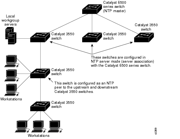
Cisco's implementation of NTP does not support stratum 1 service; it is not possible to connect to a radio or atomic clock. We recommend that the time service for your network be derived from the public NTP servers available on the IP Internet. Figure 4-2 shows a typical network example using NTP.
If the network is isolated from the Internet, Cisco's implementation of NTP allows a device to act as though it is synchronized through NTP, when in fact it has determined the time by using other means. Other devices then synchronize to that device through NTP.
When multiple sources of time are available, NTP is always considered to be more authoritative. NTP time overrides the time set by any other method.
Several manufacturers include NTP software for their host systems, and a publicly available version for systems running UNIX and its various derivatives is also available. The NTP software allows host systems to be time-synchronized as well.
Figure 4-2 Typical NTP Network Configuration
Configuring Time and Date Manually
If no other source of time is available, you can manually configure the time and date after the system is restarted. The time remains accurate until the next system restart. We recommend that you use manual configuration only as a last resort. If you have an outside source to which the WMIC can synchronize, you do not need to manually set the system clock.
Setting the System Clock
If you have an outside source on the network that provides time services, such as an NTP server, you do not need to manually set the system clock.
To set the system clock, follow these steps, beginning in privileged EXEC mode:
This example shows how to manually set the system clock to 1:32 p.m. on July 23, 2001:
bridge# clock set 13:32:00 23 July 2001Displaying the Time and Date Configuration
To display the time and date configuration, use the show clock [detail] command in privileged EXEC mode.
The system clock keeps an authoritative flag that shows whether the time is authoritative (believed to be accurate). If the system clock has been set by a timing source such as NTP, the flag is set. If the time is not authoritative, the flag is used only for display purposes. Until the clock is authoritative and the authoritative flag is set, the flag prevents peers from synchronizing to the clock when the peers' time is invalid.
The symbol that precedes the show clock display has this meaning:
•
•
•
Configuring the Time Zone
To manually configure the time zone, follow these steps, beginning in privileged EXEC mode:
The minutes-offset variable in the clock timezone command is available for those areas where a local time zone is only a percentage of an hour different from UTC. For example, the time zone for some sections of Atlantic Canada (AST) is UTC-3.5, where the 3 means 3 hours and .5 means 50 percent. In this case, the necessary command is clock timezone AST -3 30.
To set the time to UTC, use the no clock timezone command in global configuration mode.
Configuring Summer Time (Daylight Saving Time)
To configure daylight saving time in areas where it starts and ends on a particular day of the week each year, follow these steps, beginning in privileged EXEC mode:
The first part of the clock summer-time command specifies when daylight savings time begins, and the second part specifies when it ends. All times are relative to the local time zone. The start time is relative to standard time. The end time is relative to daylight savings time. If the starting month is after the ending month, the system assumes that you are in the southern hemisphere.
This example shows how to specify that summer time starts on the first Sunday in April at 02:00 and ends on the last Sunday in October at 02:00:
bridge(config)# clock summer-time PDT recurring 1 Sunday April 2:00 last Sunday October
2:00
Configuring NTP
WMICs do not have a hardware-supported clock, and they cannot function as an NTP master clock to which peers synchronize when an external NTP source is not available. These devices also have no hardware support for a calendar. As a result, the ntp update-calendar and the ntp master commands are not available.
Default NTP Configuration
Table 4-4 shows the default NTP configuration.
NTP is disabled by default.
Configuring NTP Authentication
This procedure must be coordinated with the administrator of the NTP server; the information you configure in this procedure must be matched by the servers that the WMIC uses to synchronize its time to the NTP server.
To authenticate the associations (communications between devices running NTP that provide for accurate timekeeping) with other devices, follow these steps, beginning in privileged EXEC mode:
To disable NTP authentication, use the no ntp authenticate command in global configuration mode. To remove an authentication key, use the no ntp authentication-key number command in global configuration mode. To disable authentication of the identity of a device, use the no ntp trusted-key key-number command in global configuration mode.
This example shows how to configure the WMIC to synchronize only to devices providing authentication key 42 in the device's NTP packets:
bridge(config)# ntp authenticatebridge(config)# ntp authentication-key 42 md5 aNiceKeybridge(config)# ntp trusted-key 42Configuring NTP Associations
An NTP association can be a peer association (the WMIC can either synchronize to the other device or allow the other device to synchronize to it), or it can be a server association (the WMIC synchronizes to the other device; the device does not synchronize to the WMIC).
To form an NTP association with another device, follow these steps, beginning in privileged EXEC mode:
You need to configure only one end of an association; the other device can automatically establish the association. If you are using the default NTP version (version 3), but NTP synchronization does not occur, try using NTP version 2. Many NTP servers on the Internet run version 2.
To remove a peer or server association, use the no ntp peer ip-address or the no ntp server ip-address command in global configuration mode.
This example shows how to configure the WMIC to synchronize its system clock with the clock of the peer at IP address 172.16.22.44, using NTP version 2:
bridge(config)# ntp server 172.16.22.44 version 2Configuring NTP Broadcast Service
The communications between devices running NTP (known as associations) are usually statically configured; each device is given the IP addresses of all the devices with which it should form associations. Accurate timekeeping is possible by exchanging NTP messages between associated devices. However, in a LAN environment, NTP can be configured to use IP broadcast messages instead. This alternative reduces configuration complexity because each device can be configured only to send broadcast messages or to receive broadcast messages. However, the information flow is one-way only.
The WMIC can send or receive NTP broadcast packets on an interface-by-interface basis if there is an NTP broadcast server, such as a router, broadcasting time information on the network. The WMIC can send NTP broadcast packets to a peer so that the peer can synchronize to it. The WMIC can also receive NTP broadcast packets to synchronize its own clock. This section provides procedures for sending and receiving NTP broadcast packets.
To configure the WMIC to send NTP broadcast packets to peers so that they can synchronize their clock to the WMIC, follow these steps, beginning in privileged EXEC mode:
To disable the interface from sending NTP broadcast packets, use the no ntp broadcast interface configuration command.
This example shows how to configure an interface to send NTP version 2 packets:
bridge(config)# interface gigabitethernet0/1bridge(config-if)# ntp broadcast version 2Now you are ready to configure the connected peers to receive NTP broadcast packets, as described in the next procedure. To configure the WMIC to receive NTP broadcast packets from connected peers, follow these steps, beginning in privileged EXEC mode:
To disable an interface from receiving NTP broadcast packets, use the no ntp broadcast client command in configuration mode. To change the estimated round-trip delay to the default, use the no ntp broadcastdelay command in global configuration mode.
This example shows how to configure an interface to receive NTP broadcast packets:
bridge(config)# interface gigabitethernet0/1bridge(config-if)# ntp broadcast clientConfiguring NTP Access Restrictions
You can control NTP access by using access lists.
Creating an Access Group and Assigning a Basic IP Access List
To control access to NTP services by using access lists, follow these steps, beginning in privileged EXEC mode:
The access group keywords are scanned in this order, from least restrictive to most restrictive:
1.
2.
3.
4.
If the source IP address matches the access lists for more than one access type, the first access type is granted. If no access groups are specified, all access types are granted to all devices. If any access groups are specified, only the specified access types are granted.
To remove access control to the WMIC NTP services, use the no ntp access-group {query-only | serve-only | serve | peer} command in global configuration mode.
This example shows how to configure the WMIC to allow itself to synchronize to a peer from access list 99. However, the WMIC restricts access to allow only time requests from access list 42:
bridge# configure terminalbridge(config)# ntp access-group peer 99bridge(config)# ntp access-group serve-only 42bridge(config)# access-list 99 permit 172.20.130.5bridge(config)# access list 42 permit 172.20.130.6Disabling NTP Services on a Specific Interface
NTP services are enabled on all interfaces by default.
To disable NTP packets from being received on an interface, follow these steps, beginning in privileged EXEC mode:
To reenable receipt of NTP packets on an interface, use the no ntp disable command in interface configuration mode.
Configuring the Source IP Address for NTP Packets
When the WMIC sends an NTP packet, the source IP address is normally set to the address of the interface through which the NTP packet is sent. Use the ntp source command in global configuration mode when you want to use a particular source IP address for all NTP packets. The address is taken from the specified interface. This command is useful if the address on an interface cannot be used as the destination for reply packets.
To configure a specific interface from which the IP source address is to be taken, follow these steps, beginning in privileged EXEC mode:
The specified interface is used for the source address for all packets sent to all destinations. If a source address is to be used for a specific association, use the source keyword in the ntp peer or ntp server command in global configuration mode as described in the "Configuring NTP Associations" section.
Displaying the NTP Configuration
To display NTP information, use the following commands in privileged EXEC mode:
•
•
For detailed information about the fields in these displays, see the Cisco IOS Configuration Fundamentals Command Reference for Release 12.1.
If summer time in your area does not follow a recurring pattern (configure the exact date and time of the next summer time events), follow these steps, beginning in privileged EXEC mode:
The first part of the clock summer-time command specifies when summer time begins, and the second part specifies when it ends. All times are relative to the local time zone. The start time is relative to standard time. The end time is relative to summer time. If the starting month is after the ending month, the system assumes that you are in the southern hemisphere.
To disable summer time, use the no clock summer-time command in global configuration mode.
This example shows how to set summer time to start on October 12, 2005, at 02:00, and to end on April 26, 2006, at 02:00:
bridge(config)# clock summer-time pdt date 12 October 2000 2:00 26 April 2001 2:00
![]()
![]()
![]()
![]()
![]()
![]()
![]()
![]()
Posted: Wed Feb 13 22:31:01 PST 2008
All contents are Copyright © 1992--2008 Cisco Systems, Inc. All rights reserved.
Important Notices and Privacy Statement.