|
|

Table Of Contents
Fast Ethernet Switch Mobile Interface Card
Autonegotiation and Auto-MDI/MDIX
FESMIC Rotary Switch Positions
Fast Ethernet Switch Mobile Interface Card
The Fast Ethernet Switch Mobile Interface Card is a mobile interface card (MIC) in a standard PC/104-Plus form factor. FESMICs are components of the Cisco 3200 Series Mobile Access Router. The 4-port FESMIC provides four sets of switched Fast Ethernet signals. The 2-port FESMIC provides two sets of switched Fast Ethernet signals.
The key features of the FESMIC include the following:
•
Autosensing of switched Fast Ethernet interfaces.
•
•
•
Only one FESMIC is supported in a Cisco 3200 Series router. Additional cards and components provide power and link interfaces to the FESMIC. The exact configuration of your router will vary, depending on how your vendor configured it.
Note
The FESMIC draws power from the PCI and the ISA connectors. Table 4-1 shows the estimated power consumption. Note that these are theoretical maximum wattages.
Table 4-1 FESMIC Estimated Power Consumption
+5.0 V
0.2 A
1.0 W
ISA and PCI connectors
+3.3 V
2.3 A
7.7 W
PCI connectors
Autonegotiation and Auto-MDI/MDIX
All of the Fast Ethernet interfaces support Ethernet autonegotiation for the line transmission speed. Both sides of the connection are automatically set to either 10BASE-TX or 100BASE-TX. Autonegotiation is widely used on most Ethernet interfaces, and it is the default mode.
When a Fast Ethernet interface is enabled, one end of the link must perform media-dependent interface (MDI) crossover (MDIX), so that the transmitter on one end of the data link is connected to the receiver on the other end of the data link (a crossover cable is typically used). The Auto-MDIX feature eliminates the need for crossover cabling by performing an internal crossover when a straight cable is detected during the autonegotiation phase.
If autonegotiation is disabled, Auto-MDI/MDIX cannot work because there is no signal transmission at initialization to sample the cabling with. Therefore, as in all systems not supporting the HP Auto-MDIX feature, cabling must be correct for the devices being connected. The Auto-MDIX feature is disabled if you explicitly set the line speed rather than leaving the default mode of autonegotiation. Although it is possible to disable HP Auto-MDIX with autonegotiation enabled, the current software does not implement an explicit command-line interface (CLI) command to allow you to disable Auto-MDIX during autonegotiation.
Autonegotiation Enable
To enable autonegotiation, use the following configuration:
Router#(config) FastEthernet m/nRouter#(config-if) speed autowhere m is the slot and n is the port number.
Autonegotiation Disable
To disable autonegotiation and Auto-MDIX by forcing the line speed through a manual setting, enter the following configuration commands:
Router#(config) FastEthernet m/nRouter#(config-if) speed 10or
Router#(config) FastEthernet m/nRouter#(config-if) speed 100
MAC Address Allocation
The 4-port FESMIC stores 4 unique MAC addresses for the 10/100 Ethernet interfaces. The 2-port FESMIC stores 2 unique MAC addresses for the 10/100 Ethernet interfaces. In addition, 37 MAC addresses are burned into Cisco 3270 Rugged Router card-equipped routers, and 33 MAC addresses are burned into the Mobile Access Router Card (MARC) to support the FESMIC per-VLAN spanning tree (PVST) and inter-VLAN routing features.
To provide support for up to 32 VLANs, and the 32 Spanning Tree Protocol (STP) sessions that might be running, 32 unique MAC addresses are required for the bridge packet data unit (BPDU) IDs. In addition, the FESMIC needs one MAC address for VLAN routing, bringing the total of number of MAC addresses on the wired router to 34. To support future development, the MAC addresses are burned into the Mobile Access Router Card (MARC), instead of the FESMIC.
FESMIC Component Systems
The ISA buses and PCI buses on the Cisco 3200 Series Mobile Access Router cards provide power to the components on the cards. Both buses comply with the PC/104-Plus standard. The ISA bus allows PC/104-Plus ISA signals to pass through the card bus, but the Cisco cards do not use any of the signals.
The PCI bus signals allow the Cisco cards to communicate. Non-Cisco cards cannot communicate with the Cisco 3200 Series Mobile Access Router cards over the PCI bus.
Caution
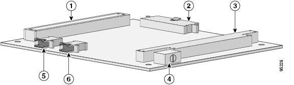
Figure 4-1 shows the 2-port FESMIC header and bus locations.
Figure 4-1 2-port FESMIC Header and Bus Locations
PCI bus
20-pin LED header
ISA bus
Rotary switch
FE0 Fast Ethernet header
FE1 Fast Ethernet header
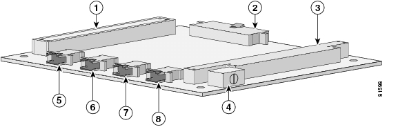
Figure 4-2 shows the 4-port FESMIC header and bus locations.
Figure 4-2 4-port FESMIC Header and Bus Locations
Note
Signals for the FESMIC
The signals are delivered through 10-pin headers, with one set of Fast Ethernet signals per header. LED signals and 5 V of power are provided through the 20-pin LED header. Cisco 3200 Series router cards do not support any ISA bus signals.
The PCI bus connector supports communication between the FESMIC, the Serial Mobile Interface Card (SMIC), and the Cisco 3270 Rugged Router card or Mobile Access Router Card (MARC). The Wireless Mobile Interface Card (WMIC) communicates with the router through an internal Fast Ethernet port and is configured through an independent console port; the WMIC draws power only from the bus.
The Fast Ethernet port signals are in compliance with IEEE 802.3. They are provided through the Ethernet headers, which support the following:
•
•
•
•
•
•
•
The Fast-Ethernet ports on the 4-port FESMIC and the 2-port FESMIC are Fast Ethernet switch ports. The switch ports support all Layer 2 features. The Fast-Ethernet 0/0 port on the Cisco 3270 Rugged Router card and MARC is a Fast Ethernet router port. The routing features supported on the MARC cannot be configured on the FESMIC ports.
FESMIC Rotary Switch Positions
A Cisco router identifies a Fast Ethernet interface address by its slot number and port number, in the form of slot/port. The slot/port addresses of the Fast Ethernet interfaces on the FESMIC depend on the position of the rotary switch.
For example, if the rotary switch on the 4-port FESMIC is in position 0, then the ports are identified as 1/0, 1/1, 1/2, and 1/3. If the rotary switch on the 2-port FESMIC is in position 0, the ports are identified as 1/0 and 1/1.
Table 4-2 shows the mapping of the switch positions to the Cisco IOS slot numbers.
Table 4-2 FESMIC Rotary Switch Positions
0
1
1
2
2
3
3-7
Not supported
Caution
•
"MIC-3-SLOTNOTSUPPORTED: The MIC cannot operate when the rotary switch is in position 3. Change the switch position to one of the supported, unused positions 0-2."
•
"Non-recoverable error occurred. Please check the rotary switch positions on the MIC cards for the possible misconfiguration of the switch position."
Table 4-3 shows the FESMIC Fast Ethernet signal assignments. The position of the rotary switch determines the port assignments. Although the rotary switch has eight positions, only one of three positions can be selected. The rotary switch position should be unique for each MIC.
Table 4-3 FESMIC Rotary Switch Positions and Signal Assignments
0
1
FE 1/0
FE 1/1
FE 1/21
FE 1/31
1
2
FE 2/0
FE 2/1
FE 2/21
FE 2/31
2
3
FE 3/0
FE 3/1
FE 3/21
FE 3/31
1 For 4-port FESMIC only.
![]()
![]()
![]()
![]()
![]()
![]()
![]()
![]()
Posted: Sun Feb 10 06:22:54 PST 2008
All contents are Copyright © 1992--2008 Cisco Systems, Inc. All rights reserved.
Important Notices and Privacy Statement.