cc/td/doc/product/access/mar_3200
hometocprevnextglossaryfeedbacksearchhelp
PDF

Table Of Contents

Serial Mobile Interface Card

SMIC Component Systems

Signals for the SMIC

4-Port SMIC Rotary Switch Positions

2-port SMIC Rotary Switch Positions

SMIC LED Signals

SMIC Power Consumption


Serial Mobile Interface Card


The Serial Mobile Interface Card is one component of the Cisco 3200 Series Mobile Access Router. It provides the router up to 4 high-speed sets of serial signals in both data terminal equipment (DTE) and data circuit equipment (DCE) modes. Additional components provide power and link interfaces to the SMIC. For example, the Cisco 3270 Rugged Router card provides the host processor, memory, and headers for the Fast Ethernet, console, and auxiliary signals for the router. The exact configuration of your router will vary, depending on how it was configured by your vendor.


Note This section provides basic information about the SMIC hardware for the purpose of performing simple troubleshooting, such as reconnecting a loose cable. To solve more difficult problems, please contact your vendor.


Each SMIC provides the following:

Support for two to four sets of serial signals with protocol support for High-Level Data Link Control (HDLC), asynchronous, synchronous and octet-oriented PPP modes. The signals can be configured to any serial standard (EIA/TIA-232, EIA/TIA-449, EIA/TIA-530, EIA/TIA-530A, EIA/TIA-X.21, or CCITT V.35).

DCE and DTE mode support on each set of serial signals.

Speeds of 2 Mbps for synchronous data transfer and 115 kbps for asynchronous data transfer on each serial interface. All serial standards reach 2 Mbps (for synchronous) except for the EIA/TIA-232 standard, which supports up to 192K.


Note The Peripheral Component Interconnect (PCI) bus and the Industry Standard Architecture (ISA) bus use keying features in the standard stacking headers to guarantee proper module installation. On the PCI bus, pin D30 is removed and its opening is plugged. On the ISA Bus, pin C19 and pin B10 are removed, and their openings are plugged.


The PCI bus connector supports communication between the SMIC, the Fast Ethernet Switch Mobile Interface Card (FESMIC), and the Cisco 3270 Rugged Router card or Mobile Access Router Card (MARC). The Wireless Mobile Interface Card (WMIC) communicates with the router through an internal Fast Ethernet port and is configured through an independent console port; the WMIC only draws power only from the bus.

SMIC Component Systems

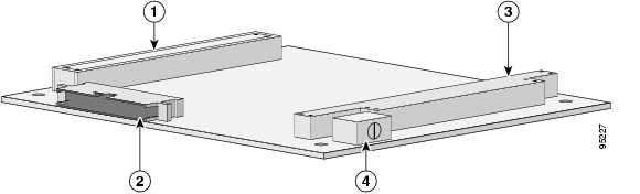
Figure 5-1 shows the 2-port SMIC header and bus locations.

Figure 5-1 2-port SMIC Header and Bus Locations

1

PCI bus

2

60-pin multifunction header for Serial 0 and Serial 1 signals

3

ISA bus

4

Rotary switch


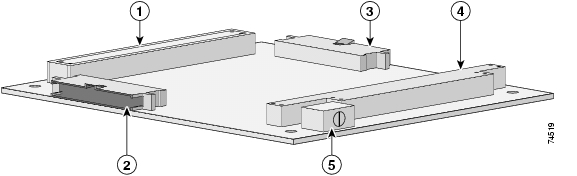
Figure 5-2 shows the 4-port SMIC header and bus locations.


Caution If you add non-Cisco cards that generate signals on the PCI bus, the router might shut down. Do not add non-Cisco cards that generate signals on the PCI bus.

Figure 5-2 4-port SMIC Header and Bus Locations

1

PCI bus

2

60-pin multifunction header for Serial 2 and Serial 3 signals

3

ISA bus

4

Rotary switch

5

60-pin multifunction header for Serial 0 and Serial 1 signals


Signals for the SMIC

The Cisco Single-sideband (SSB) Serial standard supports the following:

EIA/TIA-232, EIA/TIA-449, EIA-530, EIA-530A, X.21, and V.35 standards in both DTE and DCE modes.

Signals (SSB and LED) are provided through the 60-pin multifunction header(s).

The position of the rotary switch determines the port assignments. Although the rotary switch has eight positions, only positions 0, 1, and 2 are supported on the 4-port SMIC, and only positions 0 and 1 are supported on the 2-port SMIC.

Table 5-1 provides 4-port SMIC port assignments.

Table 5-1 4-port SMIC Rotary Switch Settings and Port Assignments

Position
MIC Slot
Port Assignments

0

1

Serial 1/0

Serial 1/1

Serial 1/2

Serial 1/3

1

2

Serial 2/0

Serial 2/1

Serial 2/2

Serial 2/3

2

3

Serial 3/0

Serial 3/1

Serial 3/2

Serial 3/3


Table 5-2 provides the 2-port SMIC port assignments.

Table 5-2 2-port SMIC Rotary Switch Settings and Port Assignments

Position
MIC Slot
Port Assignments

0

1

Serial 1/0

Serial 1/1

1

2

Serial 2/0

Serial 2/1


4-Port SMIC Rotary Switch Positions

Table 5-3 shows the 4-port SMIC serial signal assignments. The position of the rotary switch determines the port assignments. Although the rotary switch has 8 positions, only 1 of 4 positions can be selected. The rotary switch position should be unique for each mobile interface card (MIC) card.

Table 5-3 4-port SMIC Rotary Switch Positions and Serial Set Signal Assignments

Rotary Switch Position
MIC Slot
Signal Assignments

0

1

Serial 1/0

Serial 1/1

Serial 1/2

Serial 1/3

1

2

Serial 2/0

Serial 2/1

Serial 2/2

Serial 2/3

2

3

Serial 3/0

Serial 3/1

Serial 3/2

Serial 3/3

3

4

Serial 4/0

Serial 4/1

Serial 4/2

Serial 4/3


2-port SMIC Rotary Switch Positions

Table 5-4 shows the 2-port SMIC serial signal assignments. The position of the rotary switch determines the port assignments. Although the rotary switch has 8 positions, only 1 of 2 positions can be selected. The rotary switch position should be unique for each mobile interface card (MIC) card.

Table 5-4 2-port SMIC Rotary Switch Positions and Serial Set Signal Assignments

Rotary Switch Position
MIC Slot
Signal Assignments

0

1

Serial 1/0

Serial 1/1

Serial 1/2

Serial 1/3

1

2

Serial 2/0

Serial 2/1

Serial 2/2

Serial 2/3


SMIC LED Signals

Table 5-5 shows the LED signals that are supported on the SMIC, along with the corresponding functions. Serial 2 and Serial 3 apply to the 4-port SMIC only.

Table 5-5 SMIC LED Functions

LED
Function

SERIAL0 ACTIVITY

Blinks once when a packet is either transmitted from or received on Serial 0. Originates from Header 5.

SERIAL0 LINK

Indicates the status of Serial 0. Originates from Header 5. The LED is on when a serial port is in DTE mode, and when the data set ready (DSR), data carrier detect (DCD), and clear to send (CTS) signals are detected. The LED is on when a serial port is in DCE mode, and when the data terminal ready (DTR) and request to send (RTS) signals are detected.

SERIAL1 ACTIVITY

Blinks once when a packet is either transmitted from or received on Serial 1. Originates from Header 5.

SERIAL1 LINK

Indicates the status of Serial 1. Originates from Header 5. The LED is on when the serial port is in DTE mode, and when the DSR, DCD, and CTS signals are detected. The LED is on when the serial port is in DCE mode, and when the DTR and RTS signals have been detected.

SERIAL2 ACTIVITY

Blinks once when a packet is either transmitted from or received on Serial 2. Originates from Header 2.

SERIAL2 LINK

Indicates the status of Serial 2. Originates from Header 2. The LED is on when the serial port is in DTE mode, and when the DSR, DCD, and CTS signals are detected. The LED is on when the serial port is in DCE mode, and when the DTR and RTS signals have been detected.

SERIAL3 ACTIVITY

Blinks once when a packet is either transmitted FROM or received on Serial 3. Originates from Header 2.

SERIAL3 LINK

Indicates the status of Serial 3. originates from Header 2. The LED is on when the serial port is in DTE mode, and when the DSR, DCD, and CTS signals are detected. The LED is on when the serial port is in DCE mode, and when the DTR and RTS signals have been detected.


SMIC Power Consumption

The SMIC draws power from the PCI and the ISA connectors.

Table 5-6 shows the estimated power consumption. Note that these are theoretical maximum wattages.

Table 5-6 SMIC Estimated Power Consumption

Voltage
Current Draw
Power
Source

+5.0 V

1.0 A

5.0 W

ISA and PCI connectors

+3.3 V

0.5 A

1.7 W

PCI connectors


hometocprevnextglossaryfeedbacksearchhelp

Posted: Sun Feb 10 06:22:54 PST 2008
All contents are Copyright © 1992--2008 Cisco Systems, Inc. All rights reserved.
Important Notices and Privacy Statement.