|
|

Table Of Contents
Mobile Access Router Card
The Mobile Access Router Card is one component of the Cisco 3200 Series Mobile Access Router. It includes the host processor, memory, and headers for the Fast Ethernet, console, and auxiliary signals for the router. Additional components provide power and link interfaces to the MARC. For example, the 4-port Serial Mobile Interface Card (SMIC) provides up to four Smart Serial interfaces. The exact configuration of your router will vary, depending on how your vendor configured it.
Note
This section provides basic information about the MARC hardware for the purpose of performing simple troubleshooting tasks, such as reconnecting a loose cable. To solve more difficult problems, please contact your vendor.
The key features of the MARC include the following:
•
•
•
•
•
•
•
•
•
Caution
When Zeroization is not configured on the router, the AUX port functions as a modem port or a terminal port. When declassification is enabled through the CLI, we recommend that you do not use the AUX port for any other function than declassification. This is because there is no way for the router to reliably determine if a device attached to the AUX port is an actuator; therefore, any device attached to the AUX port could potentially trigger declassification.
The PCI bus connector supports communication between the Serial Mobile Interface Card (SMIC), the Fast Ethernet Switch Mobile Interface Card (FESMIC), and the Mobile Access Router Card. The Wireless Mobile Interface Card (WMIC) communicates with the router through an internal Fast Ethernet port and is configured through an independent console port; the WMIC only draws power from the bus.
MARC Component Systems
The industry-standard architecture (ISA) buses and peripheral component interconnect (PCI) buses on the Cisco 3200 Series Mobile Access Router cards provide power to the components on the cards. Both buses comply with the PC/104-Plus standard. The ISA bus allows PC/104-Plus ISA signals to pass through the card bus, but the Cisco cards do not use any of the signals.
Caution
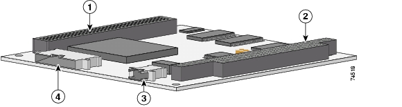
Figure 3-1 shows the MARC header and bus locations.
Figure 3-1 MARC Header and Bus Locations
Note
MARC Power Requirements
The MARC uses +3.3-V, +5-V, and +12-V power sources. Internal on-board DC-to-DC conversion circuitry generates 1.8 V/1.5 A from the +3.3-V power source.
Table 3-1 MARC Voltages
+5.0 V
0.3 A
1.5 W
+12.0 V
0.1 A
1.2 W
+3.3 V
2.0 A
6.6 W
MARC Router Signals
Cisco 3200 Series router cards do not support any ISA bus signals. The PCI bus connector supports communication between Cisco 3200 Series Mobile Access Router cards.
Note
The signals are delivered through the shared, 34-pin multifunction header and the 10-pin Ethernet header. LED signals and 5 V of power are also provided through the shared, 34-pin multifunction header.
Fast Ethernet Signals on the MARC
There is one fixed Fast Ethernet port on the MARC. A Cisco router identifies a Fast Ethernet interface address by its slot number and port number, in the format slot/port. The slot/port address of a Fast Ethernet interface on the MARC is 0/0.
The Fast Ethernet port signals are in compliance with IEEE 802.3. They are provided through the 10-pin Ethernet header, which supports the following:
•
•
•
•
•
•
•
•
•
The FastEthernet 0/0 port on the MARC is a Fast Ethernet router port. The FastEthernet ports on the 4-port FESMIC and the 2-port FESMIC are Fast Ethernet switch ports. The routing features supported on the MARC cannot be configured on the FESMIC ports.
Console and Auxiliary Signals
You can configure the console interface by using Cisco IOS command line interface (CLI) commands. The console interface and the AUX port can be accessed simultaneously. Also, the console port and the AUX port can be accessed simultaneously. For example, you can connect a terminal to the console interface and an external modem or a GPS modem to the AUX port.
The console port signals are provided through the multifunction header:
•
•
•
The AUX port is a serial asynchronous port that works at speeds of 1.2 kbps, 2.4 kbps, 4.8 kbps, 9.6 kbps, 19.2 kbps, 38.4 kbps, 57.6 kbps, and 115.2 kbps.
The AUX port supports the following:
•
•
•
•
•
•
Note
A +5-V power supply is provided for a device connected to an AUX port. Typically the +5-V power supply current to GPS modems should be limited to less than 200 mA.
![]()
![]()
![]()
![]()
![]()
![]()
![]()
![]()
Posted: Sun Feb 10 06:22:49 PST 2008
All contents are Copyright © 1992--2008 Cisco Systems, Inc. All rights reserved.
Important Notices and Privacy Statement.