|
|

Table Of Contents
Quality of Service for Cisco 3200 Routers
How Mobile IP Interacts with QoS
The Tunnel Template and Mobile IP
QoS Components Used with Mobile IP
Monitoring and Maintaining QoS for VPNs
Examples of QoS for VPNs Configuration
Traffic Shaping in a Wireless Environment
Quality of Service for Cisco 3200 Routers
QOS can be used to manage the output interface to increase efficiency by prioritizing the traffic. When the output interface is fast (for example, a Fast Ethernet connecting a single client), the probability of the packets being dropped or delayed is very low. When the output interface is slow, heavy traffic on the output interface causes congestion, resulting in dropped and delayed packets. An interface connected to an intermediate device, such as a WMIC, that forwards traffic to a slow uplink interface should have QOS configured.
QoS is a measure of performance that reflects router transmission quality and service availability. The mobile access router supports the following QoS features:
QoS Features Supported
Table 12-1 shows the QoS features supported by the Cisco 3200 Series router.
Table 12-1 Supported QoS Features
Class-based Weighted Fair Queueing (CBWFQ)
Yes
Yes
Yes1
Network Based Application Recognition (NBAR)
Yes
Yes
Yes
Class Based Packet Marking—Setting IP Precedence bits
Yes
Yes
Yes
Class Based Packet Marking—QoS Group Value
Yes
Yes
Yes
Class Based Packet Marking—Differentiated Services Code Point (DSCP)
Yes
Yes
Yes
Class Based Policer for the DSCP
Yes
Yes
Yes
Class Based Ethernet Class of Service (CoS) Matching and Marking (802.1p COS)
Yes
Yes
No
Priority Queueing
Yes
Yes
No1
Traffic Policing
Yes
Yes
Yes
Class Based Policer for the DiffServ Assured Forwarding (AF) Per Hop Behavior
Yes
Yes
Yes
Link Fragmentation and Interleaving (LFI)
Yes
N/A
N/A
Weighted Random Early Detection (WRED)
Yes
Yes
Yes1
DiffServ Compliant WRED
Yes
Yes
Yes1
Flow Based WRED
Yes
Yes
Yes1
Random Early Detection (RED)
Yes
Yes
Yes1
Low Latency Queueing (LLQ)
Yes
Yes
Yes1
LLQ for Frame Relay
Yes
N/A
N/A
Custom Queueing
Yes
Yes
No1
Weighted Fair Queueing (WFQ)
Yes
Yes
Yes1
Committed Access Rate (CAR)
Yes
Yes
Yes
Generic Traffic Shaping (GTS)
Yes
Yes
Yes
1 See the "QoS Restrictions" section in this chapter.
QoS Restrictions
When configuring the Switch Virtual Interface (SVI) on the FESMIC, the interface is not required to provide a mechanism for notifying the router that it has become congested for the QoS features shown in Table 12-2 to work properly. To work around this restriction, a Class Based Traffic Shaping with a Hierarchical (Nested) Policy Map must be configured on the SVI. Configuring Class Based Traffic Shaping with a nested QoS feature allows various congestion-based QoS features to work properly on the SVI.
Table 12-2 represents the corresponding Modular QoS CLI (MQC)-based features. In all cases, congestion is needed for the QoS feature to be activated.
For example, configuring Low Latency Queuing (LLQ) and CBWFQ on the SVI supports shows a Class Based Traffic Shaping with Nested LLQ and CBWFQ QoS policy.
policy-map llq-cbwfqclass voicepriority percent 20class videobandwidth percent 20class databandwidth percent 60! hierarchical(nested) policy mappolicy-map traffic-shape-llq-cbwfqclass ALLshape average 20000000service-policy llq-cbwfqinterface vlan 1service-policy output traffic-shape-llq-cbwfqQoS on a Wireless Device
For a complete description of the QoS for Virtual Private Network (VPN) commands in this chapter, refer to the Cisco IOS Quality of Service Solutions Command Reference. To locate documentation of other commands that appear in this chapter, use the command reference master index or search online.
Figure 12-1 is an example of a configuration that requires QOS to be applied at the Fast Ethernet VLAN interface.
Figure 12-1 QOS Fast Ethernet VLAN Interface Scenario
The Fast Ethernet port of the router is connected to the wireless device by using a 100 Mbps link. The wireless device connects to the Internet through a 5 Mbps link. In this scenario, it is possible for the router to send traffic to the wireless device at 100 Mbps. The upstream bandwidth for the bridge is only 5 Mbps, and the packets that exceed this rate are dropped randomly by the bridge. If QoS policies are applied to the 10/100 Fast Ethernet 2/0 (VLAN 1) router port, you can control how the different kinds of traffic is handled, reducing the random packet drops and delays by the wireless device.
Class-Based Traffic Shaping
Class Based Traffic Shaping with Hierarchical Policy Maps shapes the packets sent out of an interface and applies QOS when traffic exceeds the shaping limit.
The general packet flow when Class Based Traffic Shaping along with Hierarchical Policy Maps is configured is as follows:
•
A packet comes into an input interface.
•
•
Older QOS policies like Priority Queuing and Custom Queueing are applied while en-queuing and de-queuing the packets from the output queues. When Modular QoS CLI (MQC) Traffic Shaping is used to achieve QOS, the 10/100 Fast Ethernet physical interface need not get congested; when the input rate reaches above the configured traffic shaping rate, QoS features such as Low Latency Queuing (LLQ) and Class-based Weighted Fair Queueing (CBWFQ) become active. Refer to the "QoS Restrictions" section for additional information.
After the packets have left the traffic shaping Fast Ethernet interface, they arrive at the WMIC Fast Ethernet interface. The WMIC can also provide QoS to the pre-marked priority traffic by providing radio prioritization.
How Mobile IP Interacts with QoS
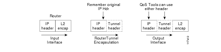
By default, Mobile IP maintains the Type of Service (ToS) byte in the IP header. In Mobile IP, the router copies the TOS (QoS) bits that are in the original IP header into the new mobile IP tunnel header before forwarding the packet to the router.
Figure 12-2 Tunnel Encapsulation
This allows the QoS is configured on the home agent and transit routers to act on the packet based on these flags.
QoS for Mobile IP tunneled packets are affected as follows:
•
•
•
Mobile IP encapsulates the original packet for forwarding to the current location of the mobile access router. Therefore, transit routers making QoS decisions evaluate the new mobile IP tunnel IP header, not the original packet header.
Mobile IP tunnel headers (as do other types of tunnel headers, such as GRE, IPSec, and so forth) present some problems to policer statements on transit routers. Assume the network administrator has assigned all voice traffic received by the router a higher priority than data traffic and the TOS bits are changed to reflect that priority. When the packet arrives at the home agent and the Mobile IP tunnel interface receives the voice packet, the TOS bits are copied into the new IP header before being forwarded to the mobile access router. Unfortunately, the transit routers might not interpret the packets as containing voice, but instead consider them as IP-in-IP packets with an unauthorized TOS level and modify the TOS bits, affecting the QoS.
This leads to another problem for the home agent. When the home agent encapsulates the original packet, it loses the information it needs to properly do QoS features that require flow information on the outbound interface.
For QoS on the outbound interface of the home agent, there is a solution to this problem. By applying qos-preclassify on the tunnel interface template, the eventual outbound interface is able to apply QoS based on the original packet. For Mobile IP headers, the router remembers where the original header is located, so QoS processing can be done at the outbound interface.
If the packet destined for the mobile access router is inbound to a foreign agent, whatever QoS parameters are configured on that foreign agent router are applied to the packet, and the same problem is created; the packet is no longer recognized as a voice packet.
The Tunnel Template and Mobile IP
Typically, when you want to offer an interface-level service or add functionality to the interface, you add a command to the interface. Adding commands to a Mobile IP interface was previously impossible because the Mobile IP tunnel interfaces are dynamically generated. The tunnel template allows you to add features to the dynamic tunnels created by Mobile IP. This template can be applied to the dynamically-generated tunnels between the home agent and foreign agents, and the dynamically generated tunnels between the home agent and mobile access routers.
The two most relevant features applied to the dynamically generated tunnels are QoS pre classification and multicast PIM sparse mode. By applying qos-preclassify to the tunnel template, the original packet header is used to classify the packet on the outbound interface using information in the original IP header instead of the Mobile IP tunnel header. This allows Qos features, such as Weighted Fair Queuing (WFQ), to see different flows at the outbound interface.
By applying the ip pim sparse mode parameter to the tunnel template, the router can to send PIM join messages back to the home agent through the mobile access router home agent tunnel (with reverse tunnel enabled).
The following example shows the configuration of tunnel template on the mobile access router:
interface Tunnel50no ip address! Allow PIM join messages to use tunnelip pim sparse-mode! Turn on Qos Pre-Classificationqos pre-classify!!ip mobile router! Mobile Router Home Addressaddress 65.1.1.1 255.255.255.0! Home Agenthome-agent 171.69.68.34! Tunnel template to use for Mobile IP Tunnelstemplate Tunnel50! Turn on Reverse Tunnel. This allows the MR to send the multicast join messages directly to the Home Agentreverse-tunnelThe following example shows the configuration of the tunnel template on the home agent:
interface Tunnel100no ip address! Allow PIM join messages to use tunnelip pim sparse-mode! Turn on Qos Pre-Classificationqos pre-classify!!! Define mobile node 65.1.1.1 as a mobile routerip mobile mobile-networks 65.1.1.1description Chamber Automobile! Tell Home Agent which mobile network this mobile router hasnetwork 172.21.58.0 255.255.255.0! Define the template to use when creating a tunnel to the mobile routertemplate Tunnel100QoS Components Used with Mobile IP
The QoS components used with Mobile IP are:
Class Map
Class maps identify interesting traffic by using access control lists (ACLs). Another method of finding interesting traffic is to match the protocol, such as RTP. A third way to find interesting traffic is to match the Differentiated Services Code Point (DSCP) field. The first two class maps match the audio and video traffic based on the protocol. The third example uses an ACL to match the Registration Request (RRQ) Packet traffic.
class-map match-all video-inmatch protocol rtp videoclass-map match-all voice-inmatch protocol rtp audioclass-map match-all rrqmatch access-group 101!access-list 101 permit udp any any eq mobile-ipPolicy Map
Policy maps use class maps to define the interesting traffic and to define what to do once the traffic is identified. The first policy map in this example, inbound-marking, changes the DSCP field of the packet and marks it as EF if it is a voice packet or AF41 if it is a video packet.
The second policy map, low-latency-queue, defines the percentage of bandwidth each class should have on the outgoing link. In class rrq, we are using a definitive percentage of the bandwidth. For example, it will always get 2 percent of the bandwidth as if it were a virtual link with that bandwidth. For class video, we specify a percentage of the remaining bandwidth after the definitive bandwidths are defined.
policy-map inbound-markingclass voice-inset ip dscp efclass video-inset ip dscp af41!policy-map low-latency-queueclass rrqpriority percent 2class voicepriority percent 50class videobandwidth remaining percent 70class highdatabandwidth remaining percent 30class class-defaultfair-queueclass-map match-all ALLmatch any!policy-map Shape20mbpsclass ALLshape average 20000000! Nesting LLQ policy under traffic shapingservice-policy low-lat-queueService Policy
The service-policy command applies the policy maps to the interfaces. In this example, the policy map, inbound-marking, is being applied to all traffic arriving on this interface. Just like ACLs are applied to inbound or outbound traffic, so can policy maps.
interface FastEthernet1/0ip address 172.69.4.1 255.255.255.0speed autofull-duplexservice-policy input inbound-markinginterface vlan 1! To workgroup brideservice-policy output Shape20Mbpsqos pre-classify Command
Some QoS features require information typically found in the IP header to function correctly. The problem is tunnel encapsulation hides the original IP header. Without the qos pre-classify command, packets traversing across the same tunnel have the same tunnel header. If there is congestion on the interface, the packets are treated the same. When the qos pre-classify command is added to the tunnel template and the tunnel template is applied to the Mobile IP tunnel where the tunnel header is added to the packet, the router can correctly identify the classification of the packet.
The qos pre-classify command behaves differently for different encapsulation headers. For non-encryption headers, for example Mobile IP headers, the router identifies the location of the beginning of the original IP header and uses the original classification during QoS processing. For encryption type headers, the router takes a snapshot of the first 64 bytes of the packet, and QoS processing is performed at the outbound interface based on the snapshot. This command is restricted to tunnel interfaces, virtual templates, and crypto maps.
For example, flow-based Weighted Fair Queuing (WFQ) classifies all packets traversing a tunnel as a single WFQ flow, even though the packets might belong to different flows with different IP source and destination addresses, source and destination ports, and so forth. By using the qos pre-classify command, the location of the QoS information in the original IP header is identified for use on the outbound interface where the QoS features that balance the traffic flows are configured.
Table 12-3 illustrates the behavior of the QOS features when pre-classification is applied. Pre-classification does not affect queuing based on other information, such as the Differentiated Services Code Point (DSCP) value.
Pre-classification Limitations
When a packet is fragmented after it has been tunnel-encapsulated (by GRE, L2TP, or IPnIP), all fragments are pre-classified by the output QOS features. However, pre-classification does not work on IP fragments that are encrypted. All fragments are classified based on the outer IPSec header only.
qos pre-classify Command
The qos pre-classify command can only be applied to a tunnel interface, virtual template interface, or crypto map configuration. The command syntax for Tunnel Interface configuration mode or crypto map configuration mode:
[no] qos pre-classifyFor GRE/IPIP tunnels, the CLI is applied on the tunnel interface. That means pre-classification can be configured on a per-tunnel basis.
For L2F/L2TP tunnels, the CLI is applied on the virtual-template interface. Every L2TP client belonging to the same VPDN group inherits the pre-classification setting. The command can be configured on a per-VPDN tunnel basis.
For IPSEC tunnels, the CLI is applied on the crypto map, allowing configuration on a per-tunnel basis. QOS features on the physical interface that carries the crypto map can classify packets prior to encryption.
WMIC QoS Configuration
After the router shapes the outgoing traffic, the packets are forwarded to the WMIC. To provide radio prioritization on the WMIC, the following commands classify the incoming marked packets and prioritizes them on the radio interface:
class-map match-all voice-inmatch ip dscp ef <?xml:namespace prefix = o ns = "urn:schemas-microsoft-com:office:office" />class-map match-all video-inmatch ip dscp 41!policy-map WirelessQoSclass voice-inset cos 6class video-inset cos 4interface Dot11Radio0!service-policy output WirelessQoSConfiguring QoS for VPNs
The QoS for VPNs feature, which is enabled by the qos pre-classify command, is restricted to tunnel and virtual template interfaces and crypto map configuration submodes.
For generic routing encapsulation (GRE) and IP in IP (IPIP) tunnel protocols, the qos pre-classify command is applied on the tunnel interface, making QoS for VPNs a configuration option on a per-tunnel basis.
For Layer 2 Forwarding (L2F) and Layer 2 Tunneling Protocol (L2TP) protocols, the qos pre-classify command is applied on the virtual template interface. L2TP clients belonging to identical virtual private dial-up network (VPDN) groups inherit the pre-classification setting. The qos pre-classify command can be configured on a per-VPDN tunnel basis.
For IPSec tunnels, the qos pre-classify command is applied on the crypto map, allowing configuration on a per-tunnel basis. QoS features on the physical interface carrying the crypto map are able to classify packets before encryption.
To configure the QoS for VPNs feature on a tunnel or virtual interface basis, use the following commands, beginning in global interface mode:
To configure the QoS for VPNs feature on the crypto map configuration basis, use the following commands, beginning in global configuration mode:
Example of QoS Configuration
The example configuration shows the tunnel template. The configuration is required only on mobile routers:
config tint tunnel100 <- or any number< any command defined inside the tunnel will be an inheritance to the mobile tunnel.>qos pre-classifyexitip mobile routertemplate tunnel 100The shut command is executed, and then the no shut command is executed on the roaming interface to implement the settings. To verify the configuration, use the show ip mobile tunnel command. The following example shows the tunnel template information.
Router#sh ip mobile tunnelMobile Tunnels:Total mobile ip tunnels 1Tunnel0:src 5.0.0.3, dest 5.0.0.2encap IP/IP, mode reverse-allowed, tunnel-users 1IP MTU 1480 bytesPath MTU Discovery, mtu: 0, ager: 10 mins, expires: neveroutbound interface Serial1/0.1MRcreated, fast switching enabled, ICMP unreachable enabled10 packets input, 1000 bytes, 0 drops59 packets output, 7906 bytesRunning template configuration for this tunnel:qos pre-classifyip rsvp bandwidth 100 100Verifying QoS for VPNs
Use the show interfaces or show crypto-map command to verify that the QoS for VPNs feature has been successfully enabled on your router.
Note
Verifying QoS for VPNs with the show interfaces Command
To verify that the QoS for VPNs feature has been successfully enabled on an interface, use the show interfaces command. The last line in the output (which is italicized for emphasis in the example) verifies that the QoS for VPNs feature is successfully enabled.
Queuing Strategy: fifo (QOS pre-classification)Router#show interfacesTunnel0 is up, line protocol is upHardware is TunnelInterface is unnumbered. Using address of Ethernet 3/2 (13.0.0.2)MTU 1476 bytes, BW 9 Kbit, DLY 500000usec,reliability 255/255. txload 1/255, rxload 1/255Encapsulation TUNNEL, loopback not setKeepalive set (10 sec)Tunnel source 13.0.0.2 (Ethernet 3/2), destination 13.0.0.1Tunnel protocol/transport GRE/IP, key disabled, sequencing disabledChecksumming of packets disabled, fast tunneling enabledLast input never, output 00:07:29, output hang neverLast clearing of "show interface" counters 1d05hQueuing Strategy: fifo (QOS pre-classification)Verifying QoS for VPNs with the show crypto map Command
To verify that the QoS for VPNs feature has been successfully enabled on a crypto map, use the show crypto map command. The last line in the output (which is italicized for emphasis in the example) verifies that the QoS for VPNs feature is successfully enabled.
Router# show crypto mapCrypto Map "testtag" 10 ipsec-isakmpPeer = 13.0.0.1Extended IP access list 102access-list 102 permit gre host 13.0.0.2 host 13.0.0.1Current peer:13.0.0.1Security association lifetime: 4608000 kilobytes/86400 secondsPFS (Y/N): NTransform sets={proposal1,}qos pre-classificationMonitoring and Maintaining QoS for VPNs
To monitor and maintain the QoS for VPNs feature, use the following commands in user EXEC mode, as needed:
Examples of QoS for VPNs Configuration
This section provides QoS for VPNs configuration examples. For additional information on how to configure QoS for VPNs, see the section "Configuring QoS for VPNs" in this chapter.
Example of Configuring QoS for VPNs for GRE and IPIP Tunnel Protocols
In the following example, tunnel0 is the tunnel name. The qos pre-classify command enables the QoS for VPNs feature on tunnel0.
Router(config)# interface tunnel0
Router(config-if)# qos pre-classify
Example of Configuring QoS for VPNs for L2F and L2TP Tunnel Protocols
In the following example, virtual-template1 is the virtual-template name. The qos pre-classify command enables the QoS for VPNs feature on virtual-template1.
Router(config)# interface virtual-template1
Router(config-if)# qos pre-classify
Example of Configuring QoS for VPNs for IPSec Tunnel Protocols
In the following example, secured-partner-X is the crypto map name. The qos pre-classify command enables the QoS for VPNs feature on secured-partner-X.
Router(config)# crypto map secured-partner-X
Router(config-crypto-map)# qos pre-classify
Traffic Shaping in a Wireless Environment
In typical scenario, the wireless device is connected internally to a Fast Ethernet port on the FESMIC to provide roaming capability. A wireless workgroup bridge has lower bandwidth than the Fast Ethernet port on the FESMIC. A heavy burst of traffic can cause packets to be dropped by the wireless device. It is necessary to shape the packets being sent out of the FESMIC Ethernet interface at rate that corresponds to uplink speed of the wireless device.
The packets are classified into different flows so each flow can be handled in accordance with the desired QoS parameters by using Class Based Traffic Shaping with Hierarchical Policy Maps.
For a brief description of how to configure QOS using Class Based Traffic Shaping along with Hierarchical Policy Maps, see "Class-Based Shaping" at: http://www.cisco.com/univercd/cc/td/doc/product/software/ios122/122cgcr/fqos_c/fqcprt4/qcfpolsh.htm.
Using access control lists for classifying the packets into various classes is not recommended as this results in the throttling of the input interface even at low loads. It is recommended that you use a separate device to classify the packets and do the marking so that the router can then classify the packets based on IP precedence by using the match ip precedence <precedence value> command.
Note
Related Documentation
For additional configuration information on the WMIC, see "Cisco 3200 Series Wireless MIC Software Configuration Guide."
For introductory QoS information:
•
•
•
Configuring QoS for VPNs: http://www.cisco.com/univercd/cc/td/doc/product/software/ios122/122cgcr/fqos_c/fqcprt1/qcfvpn.htm
12.2 QoS Configuration Guide: http://www.cisco.com/univercd/cc/td/doc/product/software/ios122/122cgcr/fqos_c/index.htm
12.2 QoS Command Reference Guide: http://www.cisco.com/univercd/cc/td/doc/product/software/ios122/122cgcr/fqos_r/index.htm
Cisco AVVID Network Infrastructure Enterprise QoS Design Guide: http://www.cisco.com/warp/customer/771/srnd/qos_srnd.pdf
![]()
![]()
![]()
![]()
![]()
![]()
![]()
![]()
Posted: Wed Nov 1 10:32:56 PST 2006
All contents are Copyright © 1992--2006 Cisco Systems, Inc. All rights reserved.
Important Notices and Privacy Statement.