|
|

Table Of Contents
FESMIC Switch Port Functionality
IP Multicast Layer 3 Switching
Enabling IP PIM on Layer 3 Interfaces
Verifying IP Multicast Layer 3 Hardware Switching Summary
Verifying the IP Multicast Routing Table
FESMIC Switch Port Functionality
The 10/100 Fast Ethernet ports on the FESMIC default to Layer 2 switch ports. The FESMIC is a "learning bridge," as defined in 802.1D with the Virtual Local Area Network (VLAN) capabilities of 802.1P/Q. The BCM5618 is fully capable of line-rate switching for all four 10/100 Fast Ethernet ports.
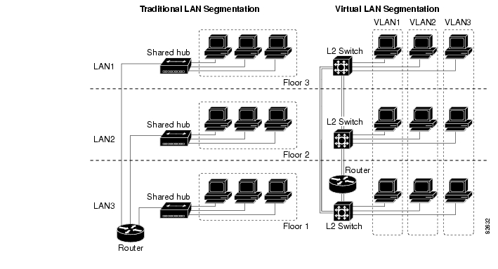
VLANs provide the segmentation services traditionally provided by routers in LAN configurations, as shown in Figure 14-1. VLANs make it easy to move an network or to change a network design.
•
Broadcast control—Just as switches physically isolate collision domains for attached hosts and only forward traffic out a particular port, VLANs provide logical collision domains that confine broadcast and multicast traffic to the bridging domain.VLANs solve the scalability problems of large flat networks by breaking a single broadcast domain into several smaller broadcast domains.
•
•
•
Figure 14-1 Traditional LAN Segmentation versus VLAN Segmentation
Port-Based VLAN
By default, the four 10/100 Fast Ethernet interfaces on the FESMIC are defaulted to Layer 2 switch ports and all four interfaces belong to VLAN 1. You can partition the switch ports to belong to different VLAN groups by using the switchport vlan access <vlan-id> command. The following is a brief function description of a FESMIC port-based VLAN:
•
•
•
•
802.1Q Trunking
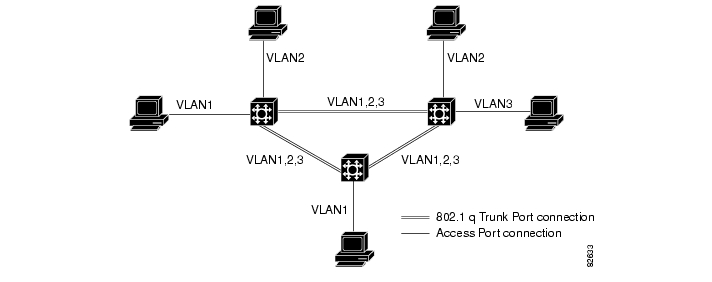
A trunk is a point-to-point link between one or more Ethernet switch ports and another networking device, such as a router or a switch. Trunks carry the traffic of multiple VLANs over a single link, and they allow you to extend VLANs across an entire network, as shown in Figure 14-2. The IEEE 802.1q protocol is an industry-standard trunking encapsulation.
Figure 14-2 802.1Q Trunk Port Application
The 802.1Q trunk port is used for VLAN extension from one switch to another 802.1Q-capable switch, and used for an 802.1Q-capable router for inter-VLAN routing. The FESMIC supports both the VLAN extension and inter-VLAN routing.
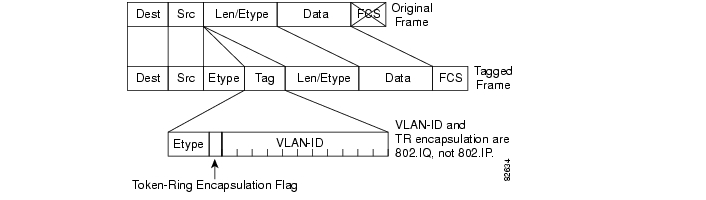
The 802.1Q uses an internal tagging mechanism. Internal tagging means that a tag is inserted within the frame. Note that on an 802.1Q trunk, one VLAN is not tagged. This VLAN, named the native VLAN, must be configured the same on each side of the trunk. We can deduce to which VLAN a frame belongs when we receive a frame with no tag. The EtherType field identifying the 802.1Q frame is 0x8100. In addition to the 12-bit VLAN-ID, 3 bits are reserved for 802.1P priority tagging, as shown in Figure 14-3. Also, note that inserting a tag into a frame that already has the maximum Ethernet size creates a 1522 byte frame, that can be considered a "baby giant" by the receiving equipment.
The FESMIC is capable of 802.1Q tagging, only supporting 802.1Q trunking encapsulation. It does not support the Cisco proprietary ISL encapsulation.
Figure 14-3 802.1Q Tag Format in an Ethernet Frame
Inter-VLAN Routing
In a VLAN network, traffic and stations for multiple network layer subnets (VLANs) can coexist on a single physical LAN segment. In practice, a single VLAN corresponds to a network subnet, and a VLAN trunking capable router is required to forward traffic from a first VLAN to a second VLAN for a Layer 2 switch.
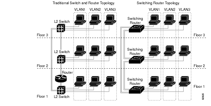
The FESMIC enables the Cisco 3200 Series router to become one of first IOS Ethernet switching routers to deliver intelligent Layer 2 switching capability and Layer 3 inter-VLAN routing in a single box solution, as shown in Figure 14-4
Figure 14-4 Switching Router Network Topology
In a typical IOS-managed Layer 2 switch, there would be one Layer 3 Switch Virtual Interface (SVI) that allows you to configure the device over a Layer 3 protocol by using SNMP or a Telnet application. This is referred to as the management VLAN for the switch. The default management VLAN is usually the native VLAN 1. The configurable VLAN device allows you to configure any VLAN to be the management VLAN, but there can be only one virtual Layer 3 interface in one VLAN.
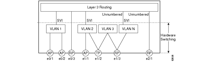
A switch routing module, like the FESMIC, allows you to use the SVI to configure more than one virtual Layer 3 interface to support routing between the different VLANs, and the virtual Layer 3 interface of any other router interface in the system, as shown in Figure 14-5.
You can manage the switching router with any switch virtual Layer 3 interface created in the system. The FESMIC router switch port is an interface capable of handling Layer 3 switching functionality in hardware. The SVI architecture has the framework to support such a functionality.
•
•
•
•
Figure 14-5 Switch Virtual Interface Architecture
VLAN Trunk Protocol (VTP)
VLAN Trunk Protocol (VTP) is a Layer 2 messaging protocol that maintains VLAN configuration consistency by managing the addition, deletion, and renaming of VLANs within a VTP domain. A VTP domain (also called a VLAN management domain) is made up of one or more switches that share the same VTP domain name and that are interconnected with trunks. VTP minimizes configuration errors and configuration inconsistencies that can result in a number of problems, such as duplicate VLAN names, incorrect VLAN-type specifications, and security violations.
The FESMIC supports both VTP version 1 and version 2.
•
•
•
VTP Server Example
The following example shows how to configure the switch as a VTP server:
Router# vlan databaseRouter(vlan)# vtp serverSetting device to VTP SERVER mode.Router(vlan)# vtp domain Lab_NetworkSetting VTP domain name to Lab_NetworkRouter(vlan)# vtp password WATERSetting device VLAN database password to WATER.Router(vlan)# exitAPPLY completed.Exiting....Router#VTP Client Example
The following example shows how to configure the switch as a VTP client:
Router# vlan databaseRouter(vlan)# vtp clientSetting device to VTP CLIENT mode.Router(vlan)# exitIn CLIENT state, no apply attempted.Exiting....Router#Disabling VTP (VTP Transparent Mode) Example
The following example shows how to configure the switch as VTP transparent:
Router# vlan databaseRouter(vlan)# vtp transparentSetting device to VTP TRANSPARENT mode.Router(vlan)# exitAPPLY completed.Exiting....Router#VTP Version 2 Example
The following example shows how to enable VTP version 2:
Router# vlan databaseRouter(vlan)# vtp v2-modeV2 mode enabled.Router(vlan)# exitAPPLY completed.Exiting....Router#802.1P CoS
The IEEE 802.1P specification defines eight levels of priority (0 thru 7), with priority 7 being the highest priority. This information is carried in the 3-bit priority field of the VLAN tag header.
The FESMIC supports up to two class of service (CoS) queues per port. For the tagged packets, the incoming packet priority can be mapped into one of the queues, based on the priority field in the tag header or from the result of filtering mechanism. For untagged packets, the CoS priority is derived either from a programmable field within the ARL (MAC address table) or from the result of filtering mechanism.
After the packets are mapped into a CoS queue, they are forwarded or conditioned using these scheduling algorithms:
•
•
The FESMIC 10/100 Fast Ethernet interfaces default to use the strict priority-based scheduling. After system boots, you can enable weighted round-robin scheduling.
Mapping 802.1P priority to IP precedence bits is not supported.
Spanning Tree Protocol (STP)
Spanning Tree Protocol (STP) is a link management protocol that provides path redundancy while preventing undesirable loops in the network. For an Ethernet network to function properly, only one active path can exist between any two stations. When two ports on a switch are in a loop, the spanning tree port priority and port path cost setting determine which port to put in the forwarding state and which port to put in the blocking state.
The 802.1Q standard defines the method for running multiple VLANs over single or multiple physical LAN segments and defines a unique spanning tree instance to be created on each of the VLAN instances for all the VLANs in a network.
A mono spanning tree (MST) network lacks some flexibility, compared to a per VLAN spanning tree (PVST) network, which runs one instance of STP per VLAN. One spanning tree is created for every new VLAN created on a FESMIC interface. STP is enabled by default on VLAN 1 and on all newly created VLANs.
Cisco developed PVST+ to allow running several STP instances (even over an 802.1Q network) by using a tunneling mechanism. Although beyond the scope of this document, PVST+ can be briefly described as utilizing a Cisco device to connect a MST zone (typically another vendor's 802.1Q-based network) to a PVST zone (typically a Cisco 802.1Q-based network). There is no specific configuration to enter in order to achieve this. PVST+ is a spanning tree that allows the coexistence of both PVST and Shared Spanning Tree Protocol (SSTP) in a mixed vendor environment.
The STP described in IEEE 802.1D standard takes a substantial amount of time to converge to a loop free topology. It fails to take advantage of the point-to-point wiring found in modern networks. PVST is enabled on all switch platforms. Rapid Spanning Tree Protocol (RSTP), specified in IEEE 802.1w[9], improves the operation of STP, while maintaining compatibility with equipment based on the (original) 802.1d Spanning Tree standard.
Note
When you connect two Cisco switches through 802.1Q trunks, the switches exchange spanning-tree bridge packet data units (BPDUs) on each VLAN allowed on the trunks. The BPDUs on the native VLAN of the trunk are sent untagged to the reserved IEEE 802.1d spanning-tree multicast MAC address (01-80-C2-00-00-00). The BPDUs on all other VLANs on the trunk are sent tagged to the reserved Shared Spanning Tree Protocol (SSTP).
One spanning tree is created for every new VLAN that is created on the FESMIC. STP is enabled by default on VLAN 1 and on all the newly created VLANs.
PVST and PVST+ are enabled by default on the FESMIC.
For detailed information on how STP works, go to http://www.cisco.com.
Switch Virtual Interface
A Switch Virtual Interface (SVI) represents a VLAN of switch ports as one interface to the routing or bridging function in the system. Only one SVI can be associated with a VLAN, but it is necessary to configure an SVI for a VLAN only when you wish to route between VLANs, fallback-bridge nonroutable protocols between VLANs, or to provide IP host connectivity to the switch. By default, an SVI is created for the default VLAN (VLAN 1) to permit remote switch administration. Additional SVIs must be explicitly configured. In Layer 2 mode, SVIs provide IP host connectivity only to the system; in Layer 3 mode, you can configure routing across SVIs.
SVIs are created the first time that you enter the vlan interface configuration command on a VLAN interface. The VLAN corresponds to the VLAN tag associated with data frames on an ISL or 802.1Q encapsulated trunk or the VLAN ID configured for an access port. Configure a VLAN interface for each VLAN for which you want to route traffic, and assign it an IP address.
SVIs support routing protocol and bridging configurations.
Creating a SVI
To make any of the 2-port FESMIC or the 4-port FESMIC switchports routable, do the following:
Step 1
Step 2
Router#vlan database! your prompt is now "Router(vlan)#"Router(vlan)#vlan 7Router(vlan)#exit
Note
Step 3
Router>conf tRouter#interface FastEthernet3/0Router(config-if)#switchport access vlan 7Step 4
Router(config-if)#interface configuration:Router(config-if)#interface vlan 7Router(config-if)#ip address 7.7.7.7 255.255.255.0The 10/100 Fast Ethernet 3/0 switchport can be pinged by through the VLAN interface. You can now attach any Layer 3 features to interface with the VLAN.
IP Multicast Layer 3 Switching
This section describes how to configure IP multicast Layer 3 switching.
You must enable IP multicast routing globally before you can enable IP multicast Layer 3 switching on Layer 3 interfaces.
For complete information and procedures, refer to these publications:
•
http://www.cisco.com/univercd/cc/td/doc/product/software/ios122/122cgcr/fipr_c/
•
http://www.cisco.com/univercd/cc/td/doc/product/software/ios122/122cgcr/fipras_r/index.htm
•
http://www.cisco.com/univercd/cc/td/doc/product/software/ios122/122cgcr/fiprrp_r/index.htm
•
http://www.cisco.com/univercd/cc/td/doc/product/software/ios122/122cgcr/fiprmc_r/index.htm
To enable IP multicast routing globally, Use this command in global configuration mode:
Enabling IP PIM on Layer 3 Interfaces
You must enable PIM on the Layer 3 interfaces before IP multicast Layer 3 switching functions on those interfaces.
To enable IP PIM on a Layer 3 interface, use the following commands beginning in global configuration mode:
This example shows how to enable PIM on an interface using the default mode (sparse-dense-mode):
Router(config-if)# ip pimRouter(config-if)#This example shows how to enable PIM sparse mode on an interface:
Router(config-if)# ip pim sparse-modeRouter(config-if)#Verifying IP Multicast Layer 3 Hardware Switching Summary
The show ip pim interface count command verifies the IP multicast Layer 3 switching enable state on IP PIM interfaces and the number of packets received and sent on the interface.
Note
Use the following show commands to verify IP multicast Layer 3 switching information for an IP PIM Layer 3 interface, as illustrated below:
Step 1
Router#show ip pim interface countState:* - Fast Switched, D - Distributed Fast SwitchedH - Hardware Switching EnabledAddress Interface FS Mpackets In/Out10.15.1.20 GigabitEthernet4/8 * H 952/423713077010.20.1.7 GigabitEthernet4/9 * H 1385673757/3410.25.1.7 GigabitEthernet4/10* H 0/3410.11.1.30 FastEthernet6/26 * H 0/010.37.1.1 FastEthernet6/37 * H 0/01.22.33.44 FastEthernet6/47 * H 514/68Step 2
Router#show ip mroute countIP Multicast Statistics56 routes using 28552 bytes of memory13 groups, 3.30 average sources per groupForwarding Counts:Pkt Count/Pkts per second/Avg Pkt Size/Kilobits per secondOther counts:Total/RPF failed/Other drops(OIF-null, rate-limit etc)Group:224.2.136.89, Source count:1, Group pkt count:29051Source:132.206.72.28/32, Forwarding:29051/-278/1186/0, Other:85724/8/56665Router#
Note
Step 3
Router#show ip interface vlan 10Vlan10 is up, line protocol is upInternet address is 10.0.0.6/8Broadcast address is 255.255.255.255Address determined by non-volatile memoryMTU is 1500 bytesHelper address is not setDirected broadcast forwarding is disabledMulticast reserved groups joined: 224.0.0.1 224.0.0.2 224.0.0.13 224.0.0.10Outgoing access list is not setInbound access list is not setProxy ARP is enabledSecurity level is defaultSplit horizon is enabledICMP redirects are always sentICMP unreachables are never sentICMP mask replies are never sentIP fast switching is enabledIP fast switching on the same interface is disabledIP Flow switching is disabledIP CEF switching is enabledIP Fast switching turbo vectorIP Normal CEF switching turbo vectorIP multicast fast switching is enabledIP multicast distributed fast switching is disabledIP route-cache flags are Fast, CEFRouter Discovery is disabledIP output packet accounting is disabledIP access violation accounting is disabledTCP/IP header compression is disabledRTP/IP header compression is disabledProbe proxy name replies are disabledPolicy routing is disabledNetwork address translation is disabledWCCP Redirect outbound is disabledWCCP Redirect exclude is disabledBGP Policy Mapping is disabledIP multicast multilayer switching is enabledIP mls switching is enabledRouter#Verifying the IP Multicast Routing Table
Use the show ip mroute command to verify the IP multicast routing table.
Step 1
Router# show ip mroute 230.13.13.1IP Multicast Routing TableFlags:D - Dense, S - Sparse, s - SSM Group, C - Connected, L - Local,P - Pruned, R - RP-bit set, F - Register flag, T - SPT-bit set,J - Join SPT, M - MSDP created entry, X - Proxy Join Timer RunningA - Advertised via MSDP, U - URD, I - Received Source Specific HostReportOutgoing interface flags:H - Hardware switchedTimers:Uptime/ExpiresInterface state:Interface, Next-Hop or VCD, State/Mode(*, 230.13.13.1), 00:16:41/00:00:00, RP 10.15.1.20, flags:SJCIncoming interface:GigabitEthernet4/8, RPF nbr 10.15.1.20Outgoing interface list:GigabitEthernet4/9, Forward/Sparse-Dense, 00:16:41/00:00:00, H(*, 230.13.13.2), 00:16:41/00:00:00, RP 10.15.1.20, flags:SJCIncoming interface:GigabitEthernet4/8, RPF nbr 10.15.1.20, RPF-MFDOutgoing interface list:GigabitEthernet4/9, Forward/Sparse-Dense, 00:16:41/00:00:00, H(10.20.1.15, 230.13.13.1), 00:14:31/00:01:40, flags:CJTIncoming interface:GigabitEthernet4/8, RPF nbr 10.15.1.20, RPF-MFDOutgoing interface list:GigabitEthernet4/9, Forward/Sparse-Dense, 00:14:31/00:00:00, H(132.206.72.28, 224.2.136.89), 00:14:31/00:01:40, flags:CJTIncoming interface:GigabitEthernet4/8, RPF nbr 10.15.1.20, RPF-MFDOutgoing interface list:NullRouter#
Note
Storm Control
A packet storm occurs when a large number of broadcast, unicast, or multicast packets are received on a port. Forwarding these packets can cause the network to slow down or to time out. Storm control is configured for the switch as a whole, although it operates on a per-interface basis. By default, storm control is disabled.
Storm control prevents switch ports on a LAN from being disrupted by a broadcast, multicast, or unicast storm on one of the interfaces. A LAN storm occurs when packets flood the LAN, creating excessive traffic and degrading network performance. Errors in the protocol-stack implementation or in the network configuration can cause a storm.
Storm control monitors incoming traffic statistics over a time period and compares the measurement with a predefined suppression level threshold. The threshold represents the percentage of the total available bandwidth of the port. If the threshold of a traffic type is reached, further traffic of that type is suppressed until the incoming traffic falls below the threshold level.
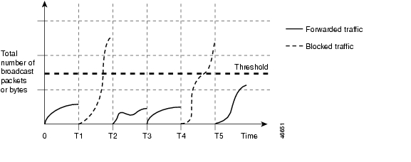
The graph in Figure 6 shows broadcast traffic patterns on an interface over a given period of time. In this example, the broadcast traffic exceeded the configured threshold between time intervals T1 and T2 and between intervals T4 and T5. When the amount of specified traffic exceeds the threshold, all traffic of that kind is dropped. Therefore, broadcast traffic is blocked during those intervals. At the next time interval, if broadcast traffic does not exceed the threshold, it is again forwarded.
Figure 6 Broadcast Suppression Example
When storm control is enabled, the switch monitors the packets that are passing from an interface to the switching bus and determines whether the packet is unicast, multicast, or broadcast. The switch monitors the number of broadcast, multicast, or unicast packets received within the 1-second time interval, and when a threshold for one type of traffic is reached, that type of traffic is dropped. This threshold is specified as a percentage of the total available bandwidth that can be used by broadcast (multicast or unicast) traffic.
The combination of broadcast suppression threshold numbers and the 1-second time interval control the way the suppression algorithm works. A higher threshold allows more packets to pass through. A threshold value of 100 percent means that no limit is placed on the traffic.
Note
The switch continues to monitor traffic on the port. When the utilization level falls back below the threshold level, the type of traffic that was dropped is forwarded again.
Use the storm-control broadcast, storm-control multicast, and storm-control unicast global configuration commands to set up the storm control threshold value.
Storm Control Configuration
This section describes how to configure storm control on your router. It consists of the following configuration information and procedures:
By default, unicast, broadcast, and multicast suppression is disabled on the switch.
Enabling Storm Control
Enable storm-control globally and enter the percentage of total available bandwidth that you want to be used by a all traffic (multicast, unitcast,); entering 100 percent would allow all traffic.
To enable a particular type of storm-control, use the following commands beginning in privileged EXEC mode:
Verifying Storm Control
Use the show storm-control command to view switch port characteristics, including the storm control levels set on the interface.
To verify storm-control statistics on an interface, use the following commands, beginning in privileged EXEC mode:
IGMP Snooping
Internet Group Management Protocol (IGMP) snooping allows the switch to "listen in" on the IGMP conversation between hosts and routers. When a switch "hears" an IGMP report from a host for a given multicast group, the switch adds the host's port number to the Group Destination Address (GDA) list for that group. And, when the switch hears an IGMP leave, it removes the host's port from the content-addressable memory (CAM) table entry.
The purpose of IGMP snooping is to restrain multicast traffic in a switched network. By default, a LAN switch floods multicast traffic within the broadcast domain, and this can consume a lot of bandwidth if many multicast servers are sending streams to the segment.
Multicast traffic is flooded because a switch usually learns MAC addresses by looking into the source address field of all the frames it receives. But, since a multicast MAC address is never used as source address for a packet and since the addresses do not appear in the MAC address table, the switch has no method for learning the addresses.
IGMP Snooping Configuration
IGMP snooping is enabled by default on a VLAN. Multicast routing has to be enabled on the router first and then PIM (Multicast routing protocol) has to be enabled on the VLAN interface so that the switch acknowledges the IGMP join and leave messages which are sent from the hosts connected to the switch. For example:
Router(config)#ip multicast-routingRouter(config-if)#interface VLAN1ip-address 192.168.10.1 255.255.255.0ip pim sparse-modeTo verify multicasting support, use the show ip igmp group command:
Router#show ip igmp groupTo verify IGMP snooping, use the show mac-address-table multicast igmp-snooping command:
Router#show mac-address-table multicast igmp-snoopingTo verify the multicast routing table, use the show ip mroute command:
Router#sh ip mroute
![]()
![]()
![]()
![]()
![]()
![]()
![]()
![]()
Posted: Wed Oct 24 15:37:10 PDT 2007
All contents are Copyright © 1992--2007 Cisco Systems, Inc. All rights reserved.
Important Notices and Privacy Statement.