|
|

This chapter describes the procedure for creating an AccessPath stack in Cisco AccessPath Manager (APM). For information on the configuration of individual AccessPath shelves, see Chapter 4, "Configuring AccessPath Shelves Using APM."
Each AccessPath system is added to APM by first adding a stack, and then adding all of the shelves (access servers, routers, and switches) that make up that stack. After you have finished adding each shelf, you can set up APM to download the configuration (based on your choices in the shelf creation process) to that shelf.
You can modify stacks and shelves to accommodate changes you make in your AccessPath system or its network connections using procedures similar to those you used to create the stacks and shelves.
Note This chapter contains general information on configuring AccessPath-TS and AccessPath-TS3 stacks. For information on special requirements for the creation of AccessPath-LS3 stacks, see the section "ExampleConfiguring a Cisco AccessPath-LS3 System" in Chapter 5, "Managing Configuration Templates with APM."
This chapter contains the following sections:
APM can configure three stack types. These types, and the number of Access Server Shelves and Router Shelves in each of their configurations are explained in Table 3-1.
| Stack Type | Number of Cisco 7206s | Number of Cisco AS5200s or AS5300s |
|---|---|---|
The procedures for creating or modifying a stack are similar but not identical.
Despite these differences in how shelves are configured, this section will show screens for the Create Stack procedure in order to describe both Create Stack and Stack Modify.
Creating or modifying a stack in APM involves two procedures, which must be completed in this order:
1. Create or modify the stack See the following sections:
(a). "Configure Stack General Information"
(b). "Configure Stack Addressing"
(c). "Configure Network Management"
(d). "Configure Security"
2. Add (or modify) all of the shelves in the stack that you would like to add or modify at this time. (See Chapter 4, "Configuring AccessPath Shelves Using APM.")
To create a stack, you must supply information for all fields presented in bold in each dialog box of the stack creation screens.
Note Pull-down menus and data-entry fields will be disabled if your previous configuration choices make them unnecessary.
Configuring the general information for your AccessPath stack involves four screens. Follow the procedures in Tables 3-2 through 3-5 and see Figures 3-1 through 3-4.
| Step | Description |
|---|---|
| 1. Click Create Stack. | When you click the Create Stack button, the first General Information dialog box appears. (See Figure 3-1.) |
| 2. Enter a stack name. | This case-sensitive stack group authentication name must be unique in the rack. |
| 3. (Optional.) Enter a stack description. | |
| 4. Select a stack type. | APM configures three kinds of AccessPath stacks:
|
| 5. Select the number of 7206(s) in the stack. | The maximum number of Cisco 7206s for all stack types that use a Catalyst 5000 Series Switch Shelf is 2. The AP-TS3 stack without a Catalyst 5002 uses only one Cisco 7206. (See Table 3-1.) |
| 6. Select the number of NAS(es)1 in the stack. | The number of Access Server Shelves (Cisco AS5200s or AS5300s) in the stack. The number and type of Access Server Shelves is limited depending on your configuration. (See Table 3-1.) |
| 7. Click Next. | The second General Information dialog box appears. (See Figure 3-2.) |
| 1NAS = network access server. |
When the second Stack General Information dialog box appears (Figure 3-2), proceed with the steps in Table 3-3.
| Step | Description |
|---|---|
| 1. (Optional.) Enter a Cisco IOS enable password and verify it by entering it again. | The Cisco IOS enable password requires that network administrators enter a password to access privileged EXEC mode. This prevents non-administrators from getting access to the EXEC mode. |
| 2. Enter a Cisco IOS enable secret password and verify it by entering it again. | The Cisco IOS enable secret password is encrypted so that it cannot be read when crossing a network. After you issue this command, the encryption cannot be reversed. The encrypted version of the password appears in output of the show running-config and show startup-config commands. The enable secret password has precedence over the enable password. Do not enter the same password as the enable password. If the two passwords are the same, the enable secret password is not a secret, because the enable password appears in the output of the show running-config and show startup-config commands. |
| 3. Enter a Cisco IOS line password and verify it by entering it again. | To provide access control on a terminal line by entering the password and establishing password checking. |
| 4. Enter a Cisco IOS SGBP1 password and verify it by entering it again. | To establish a username-based authentication system, the stack password is used to access the name argument. The stack password must be from 1 to 25 characters and must be the last option specified in the username command. |
| 5. Enter an EIGRP2 Autonomous System Number. | The number of processes that identify the routes to the other EIGRP routers. It is also used to tag the routing information. If you have an autonomous system number, you can use it for the process number. |
| 6. Click Next. | The third General Information dialog box appears. (See Figure 3-3.) |
| 1SGBP = Stack Group Bidding Protocol.
2EIGRP = Enhanced Interior Gateway Routing Protocol. |
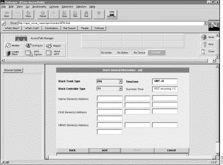
When the third Stack General Information dialog box appears (see Figure 3-3), proceed with the steps in Table 3-4.
| Step | Description |
|---|---|
| 1. Select a stack trunk type. | Trunk type supported by your service provider. The available choices include: |
| 2. Select a stack controller type. | Controller type (T1 or E1) that accepts incoming calls and sends outgoing calls through ISDN1 PRI lines. (For all selections of Stack Trunk Type except PRI, this will default to the correct selection for your network.) |
| 3. Verify your time zone. | Default value for your time zone will be retrieved from your local host. Time zones are expressed relative to Greenwich Mean Time (GMT). Verify that this field has the correct value. |
| 4. (Optional.) Configure your system with your local summer time (daylight savings time). | Daylight savings time, the default value is: This means that daylight savings time (in this case, PDT—Pacific Daylight Time) begins on the first Sunday in April at 2:00 a.m. and ends on the last Sunday in October at 2:00 a.m. Edit this text for your situation. If your area does not have daylight savings time, change this field to blank. |
| 5. (Optional.) Specify your name server address(es). | One or more domain name servers to resolve host names and IP addresses. |
| 6. (Optional.) Specify your DNS server address(es). | Dial-in clients using PPP2 applications such as CiscoRemote and Windows 95 need Domain Name System (DNS) address information as described in RFC 1877. Enter the server address to enable remote users to gather DNS information transparently as part of the PPP negotiation. |
| 7. (Optional.) Specify your NBNS Server Address(es). | Dial-in clients using PPP applications such as CiscoRemote and Windows 95 need NetBIOS name service (NBNS) address information as described in RFC 1877. Enter the server address to enable remote users to gather NBNS information transparently as part of the PPP negotiation. |
| 8. Click Next. | The fourth General Information dialog box appears. (See Figure 3-4.) |
| 1ISDN = Integrated Services Digital Network.
2PPP = Point-to-Point Protocol. |
When the fourth Stack General Information dialog box appears (see Figure 3-4), proceed with the steps in Table 3-5.
| Step | Description |
|---|---|
| 1. Select your framing. | Type of transmission unit used in the T1 or E1 link. |
| 2. Select a linecode. | Variety of Zero Code Suppression used on the link, which in turn affects a number of its characteristics. |
| 3. (An option for AS5300-based AccessPath systems using PRI, T1/PRI, or E1/PRI trunk types.) Disable or enable VPDN support. | Select Yes or No to enable or disable Virtual Private Dialup Network (VPDN) support. If you select No, none of the shelves in this stack will be able to support VPDN. Selecting Yes allows for a mixed configuration in which some shelves support VPDN and some do not. (You will configure the use of VPDN on a shelf-by-shelf basis when you create the shelves in the stack. See Chapter 4, "Configuring AccessPath Shelves Using APM.") |
| 4. (PRI trunk type only.) Select your ISDN switch type. | ISDN switch type for your T1 or E1 PRI lines. You should obtain the correct switch type from your ISDN service provider (telco). Available choices include: Your selection will be provided to the Access Server Shelves in the stack by default. |
| 5. (PRI trunk type only.) Select a signaling method. | Cisco AS5200 and Cisco AS5300 support channel associated signaling for channelized T1/E1 lines. Typically all channels of a channelized T1 or E1 line are used for analog calls. However, the Cisco AS5200 and Cisco AS5300 require a signal converter to perform conversions between R2 signaling and ear and mouth (E&M) signaling. The Cisco AS5200 supports E&M signaling on its T1/E1 controllers. |
| 6. (E1 R2 configurations only.) Select a CAS1 custom country. | If you have selected E1 R2 signalling, you may need to select a country customization for this signalling. The options include: |
| 7. Select your stack channel type. | Channel Type servicing your T1 PRI or E1 PRI lines. The Channel Type can be: |
| 8. Configure whether or not users can perform EXEC-level commands. | Select Yes to allow users to access the EXEC facility and start EXEC sessions. Select No to refuse access to the EXEC facility to all but APM administrators. |
| 9. Set the external host name for CHAP to use. | Set the Challenge Handshake Authentication Protocol (CHAP) name that the remote users will see when they dial in. |
| 10. Click Next. | The Stack Addressing dialog box appears. (See Figure 3-5.) |
| 1CAS = Channel Associated Signalling. |
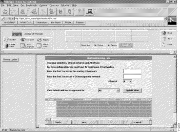
For information on configuring stack addressing, see Figure 3-5 and Table 3-6.
| Step | Description |
|---|---|
| 1. Enter the first 3 octets of the starting /24 network. | Depending on the AccessPath configuration you have specified, this screen will tell you how many contiguous class C (/24) networks you will need. In this field, enter the first 3 octets of the network address for the first class C network. APM will use this information to create IP addresses for the ports in your AccessPath system. |
| 2. Enter the first 3 octets of your management network. | In addition to your data network, you will need a management network. This network will be: Enter the first 3 octets of the IP address of your management network. |
| 3. Enter the 4th octet. | Select the 4th octet of the starting class C network address. |
| 4. (Optional.) Click Show Default IP. | Click this button to view the IP addressing on your AccessPath shelves. |
| 5. (Optional.) Select a shelf type to show address assignment for. | Use this pull-down menu to select the shelves for which you want to see the planned IP addressing. Select from: Click Update View to view the IP addressing scheme for the shelf you have selected. |
| 6. Click Next. | The Network Management dialog box appears. (See Figure 3-6.) |
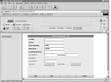
For information on configuring network management, see Figure 3-6 and Table 3-7.
| 1SNMP = Simple Network Management Protocol.
2NTP = Network Time Protocol. |
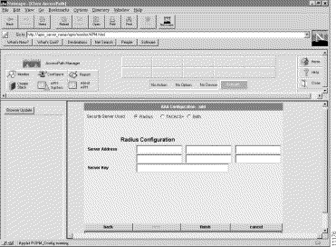
For information on configuring security, see Figure 3-7 and Table 3-8.
| Step | Description |
|---|---|
| 1. Configure the type of security server used. | Select TACACS+1, RADIUS2, or both as your remote security database. |
| 2. Configure the security server. | If you selected both TACACS+ and RADIUS, this selection will appear, allowing you to configure TACACS+ and RADIUS service separately. You may also select Advanced to configure TACACS+ or RADIUS servers to provide specific security services. (See Step 5 below.) |
| 3. Configure the security server IP address. | IP address of the remote TACACS+ or RADIUS server host. This host is typically a UNIX system running TACACS+ or RADIUS software. |
| 4. Configure a server key. | Shared secret text string used between the Access Server Shelf and the TACACS+ or RADIUS server. The Access Server Shelf and TACACS+ or RADIUS server use this text string to encrypt passwords and exchange responses. |
| 5. Configure advanced server features. | If you have selected both TACACS+ and RADIUS, after you enable AAA3 globally on the access server, you must define authentication method lists, which you then apply to lines and interfaces. These authentication method lists are security profiles that indicate the protocol (ARAP4 or PPP5) or login and authentication method (TACACS+, RADIUS, or local authentication). This screen allows you to specify whether TACACS+ or RADIUS will provide authentication for the following services: |
| 6. If you are creating a stack, click Finish. | Clicking Finish means you have finished everything but the downloading of the configuration. |
| 7. (Optional.) Click Browser Update. |
| 1TACACS+ = Terminal Access Controller Access Control System.
2RADIUS = Remote Access Dial-In User Service. 3AAA = authentication, authorization, and accounting. 4ARAP = AppleTalk Remote Access Protocol. 5PPP = Point-to-Point Protocol. |
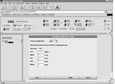
To submit and schedule a stack modification, see Figure 3-8 and Table 3-9.
Use this procedure to view a stack. You cannot use the stack view feature to change the value of any field. If you need to modify a stack, see the section "Creating or Modifying a Stack".
Step 2 Click Configure.
Step 3 Click Stack View.
Step 4 Click Execute.
Step 5 Click Next to move through the screens. (For an explanation of the data fields in these screens, refer to "Creating or Modifying a Stack".)
Step 2 Click Configure.
Step 3 Click Stack Delete.
Step 4 Click Execute.
Step 5 Click Next to move through the seven screens that show the configuration of the shelf you want to delete. For an explanation of the data fields in these screens, refer to "Creating or Modifying a Stack".
Step 6 When you reach the eighth screen, Scheduling Configuration, you can schedule the stack deletion.
Step 7 If this is the correct stack, and you are sure you want to delete it and all of its historical data, click Finish. Otherwise, click Cancel.
This completes the procedure for deleting a stack.
![]()
![]()
![]()
![]()
![]()
![]()
![]()
![]()
Posted: Mon Jan 20 22:01:28 PST 2003
All contents are Copyright © 1992--2002 Cisco Systems, Inc. All rights reserved.
Important Notices and Privacy Statement.