|
|

This chapter describes the procedure for creating and modifying AccessPath shelves in Cisco AccessPath Manager (APM).
Each AccessPath system is added to APM by first adding a stack, and then adding all of the shelves (access servers, routers, and switches) that make up that stack. After you have finished adding each shelf, you can have APM download to that shelf the configuration file based on your choices in the shelf creation process.
You can modify stacks and shelves to accommodate changes you make in your AccessPath system or its network connections using procedures similar to those you used to create the stacks and shelves. Additionally, APM allows you to view, delete, or restore these shelves.
Note This chapter contains general information on configuring AccessPath-TS and AccessPath-TS3 shelves. For information on special requirements for the creation of AccessPath-LS3 shelves, see the section "ExampleConfiguring a Cisco AccessPath-LS3 System" in Chapter 5, "Managing Configuration Templates with APM."
Cisco APM allows you to configure AccessPath shelves in the following ways:
To add a shelf to a stack or modify a shelf in a stack, follow these steps.
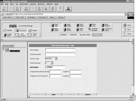
The first Shelf Global Information screen will appear. (See Figure 4-1.)
Step 2 Enter your configuration information in the screens as they appear. Click Next between screens.
Detailed procedures for adding or modifying shelves are found in the following sections. (The Shelf Add and Shelf Modify procedures are virtually identical, but the examples will use the Shelf Add procedure and screens.) The steps are as follows:
(a). "Configure Shelf Global Information"
(b). "Configure the Shelf Trunk Interface (Cisco AS5200 and Cisco AS5300 Shelves Only)"
(c). "Configure the Shelf Addresses"
You must supply information for all fields presented in bold in each dialog box. (Note that pull-down menus will be disabled if your previous stack or shelf configuration choices make them unnecessary.)
Note If any previously failed configuration record exists on the stack, then a table will display listing all the failed records. Select the failed configuration record you want to recover and click Recover. Or click Show Log to see the error log. Otherwise, click Continue to add a new shelf.
Configure the information in the Shelf Global Information screen (see Figure 4-1) as the first step in either the Shelf Add or Shelf Modify procedure. (See Table 4-1 for a detailed procedure for configuring this information.)
| Step | Description |
|---|---|
| 1. (Optional.) Enter a description of the shelf. | |
| 2. (Optional.) Enter a serial number. | |
| 3. Select a device type. | Select a device type. The device types displayed in this menu depend on two things: |
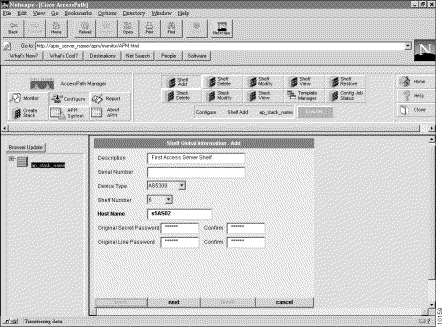
| 4. Select a shelf number. | The shelf number is a unique identifier of the shelf telling where it is located in the stack. This pull-down menu displays only the shelf numbers that are available for the device type you are adding and depends on the stack type and the shelves that you might have already added to the stack. Note When configuring the first Access Server Shelf in an AccessPath-TS3 with a Catalyst 5000 switch (as opposed to a Catalyst 5002 switch or no standalone switch), skip Shelf 5 and select Shelf 6. (See Figure 4-2.) |
| 5. Enter a host name. | A case-sensitive unique name for the shelf. The default host name contains the stack ID, the device type, and the shelf number. For example, s5AS01 would be the first Access Server shelf in a stack with the stack ID s5. |
| 6. (Optional.) Enter an original secret password. | When APM enters the enable mode, if the secret password was preconfigured to the device, then it will prompt APM for the original secret password. Note If the device is configured for an original line password and you do not enter one here, or enter an incorrect password, the shelf configuration will fail. |
| 7. (Optional.) Enter an original line password. | When APM Telnets into the device, if the line password was preconfigured to the device, then it will prompt APM for the original line password. Note If the device is configured for an original line password and you do not enter one here, or enter an incorrect password, the shelf configuration will fail. |
| 8. Continue with either "Configure the Shelf Trunk Interface (Cisco AS5200 and Cisco AS5300 Shelves Only)" or "Configure the Shelf Addresses," depending on the kind of shelf you are configuring. |
|
Configuring the Shelf Trunk Interface is the second step in either the Shelf Add or Shelf Modify procedure for Cisco AS5200 and Cisco AS5300 shelves only. (See Figure 4-3 and Table 4-2 for instructions.)
| Step | Description |
|---|---|
| 1. Select your framing. | Type of transmission unit used in the T1 or E1 link. |
| 2. Select a linecode. | Variety of Zero Code Suppression used on the link, which in turn affects a number of its characteristics. |
| 3. Select a trunk type. | Trunk type of the shelf. Valid selections (which will be limited depending on the configuration of the stack) include: |
| 4. (PRI trunk type only.) Select an ISDN1 switch type. | ISDN switch type that services your T1 or E1 PRI lines. You should obtain the correct switch type from your ISDN service provider (telco). |
| 5. (PRI trunk type only.) Select a signaling method. | The Cisco AS5200 and Cisco AS5300 support Channel Associated Signaling for channelized T1/E1 lines. Typically all channels of a channelized T1 or E1 line are used for analog calls. However, the Cisco AS5200 and Cisco AS5300 require a signal converter to perform conversions between R2 signaling and ear and mouth (E&M) signaling. The Cisco AS5200 supports E&M signaling on its T1/E1 controllers. |
| 6. (E1 R2 configurations only.) Select a CAS2 custom country. | If you have selected E1 R2 signalling, you may need to select a country customization for this signalling. The options include: |
| 7. (PRI trunk type only.) Select whether or not you will use multiple B channels. | Select Yes or No depending on whether this shelf will be using multiple B channels. |
| 8. (An option for AS5300-based AccessPath systems using PRI, T1/PRI, or E1/PRI trunk types, where VPDN Enabled was selected during the Stack Create or Stack Modify process.) | Select Yes or No to enable or disable Virtual Private Dialup Network (VPDN) support. |
| 9. Continue with the next section "Configure the Shelf Addresses." | Depending on the type of shelf you are configuring, proceed as follows: |
| 1ISDN = Integrated Services Digital Network.
2CAS = Channel Associated Signalling. |
The Shelf Address screens, which make up the third step in either the Shelf Add or the Shelf Modify procedure, vary depending on the shelf you are adding or modifying. Use the appropriate procedure for your shelf.
| Step | Description |
|---|---|
| 1. Configure the Ethernet address. | |
| 2. Configure the Ethernet mask. | |
| 3. Configure the Loopback1 address. | |
| 4. Configure the Loopback1 mask. | |
| 5. Configure the Asyn17 IP address. | IP address used for the remote dial-in out-of-band management. |
| 6. Configure the Asyn17 IP mask. | Subnet mask used for the remote dial-in out-of-band management. |
| 7. Configure the Serial 1 IP address. | IP address for the connection to management WAN or offload02. |
| 8. Configure the Serial 1 IP mask. | Subnet mask for the connection to management WAN or offload02. |
| 9. Configure the shelf configuration parameters. | Continue with the section "Configure the Shelf Configuration Parameters". |
| Step | Description |
|---|---|
| 1. Configure the Ethernet 1/0 address. | |
| 2. Configure the Ethernet 1/0 mask. | |
| 3. Configure the Ethernet 1/1 address. | |
| 4. Configure the Ethernet 1/1 mask. | |
| 5. Configure the Loopback1 address. | |
| 6. Configure the Loopback1 mask. | |
| 7. Configure the Async 129 IP address. | IP address used for the remote dial-in out-of-band management. |
| 8. Configure the Async 129 IP mask. | Subnet mask for the connection to remote dial-in out-of-band management. |
| 9. Configure the shelf configuration parameters. | Continue with the section "Configure the Shelf Configuration Parameters". |
| Step | Description |
|---|---|
| 1. Configure the Fast Ethernet address. | |
| 2. Configure the Fast Ethernet mask. | |
| 3. Configure the Ethernet address. | |
| 4. Configure the Ethernet mask. | |
| 5. Configure the Loopback0 address. | Virtual IP interface carrying all the dial-in users, and it exists only in the Access Server Shelves and the Router Shelf (in AccessPath-TS systems). Assign an IP network number to the loopback interface, then let each asynchronous interface borrow this network number. |
| 6. Configure the Loopback0 mask. | |
| 7. Configure the Loopback1 address. | |
| 8. Configure the Loopback1 mask. | |
| 9. Configure the beginning and ending IP local pool addresses. | IP local pool is a pool of IP addresses that exists inside the Access Server Shelves and AccessPath-TS Router Shelves, all of which are on the same IP subnet as loopback interface 0. (In AccessPath-TS3 systems, the loopback interface 0 is on the first class C network but the IP pool addresses begin in the second class C network.) |
| 10. Configure the shelf configuration parameters. | Continue with the section "Configure the Shelf Configuration Parameters". |
| Step | Description |
|---|---|
| 1. Configure the default route. | Static route that can be overridden by dynamic routing information. |
| 2. Configure the FE1/0 primary address. | |
| 3. Configure the FE1/0 primary mask. | |
| 4. (AccessPath-TS systems only.) Configure the FE1/0 secondary address. | Fast Ethernet secondary IP address used for SNMP management. |
| 5. (AccessPath-TS systems only.) Configure the FE1/0 secondary mask. | Fast Ethernet secondary subnet mask used for SNMP management. |
| 6. (AccessPath-TS systems only.) Configure the Loopback0 address. | Virtual IP interface carrying all the dial-in users, and it exists only in the Access Server Shelves and the Router Shelf (in AccessPath-TS systems). Assign an IP network number to the loopback interface, then let each asynchronous interface borrow this network number. |
| 7. (AccessPath-TS systems only.) Configure the Loopback0 mask. | |
| 8. Configure the Loopback1 address. | |
| 9. Configure the Loopback1 mask. | |
| 10. (AccessPath-TS systems only.) Configure the FE backdoor address. | IP address of the Fast Ethernet interface that is used as a backdoor interface for AccessPath-TS systems. |
| 11. (AccessPath-TS systems only.) Configure the FE backdoor mask. | Subnet mask of the Fast Ethernet interface that is used as a backdoor interface for AccessPath-TS systems. |
| 12. (AccessPath-TS systems only.) Configure the Aux Async 1 address. | Assign an address to use an external modem on the Cisco 7206's auxiliary port. |
| 13. (AccessPath-TS systems only.) Configure the beginning and ending IP local pool addresses. | Pool of IP addresses that exists inside the Access Server Shelves and AccessPath-TS Router Shelves configured for E1, all of which are on the same IP subnet as loopback interface 0. (In AccessPath-TS Router Shelves configured for T1, the loopback interface 0 is on the first class C network but the IP pool addresses begin in the second class C network.) |
| 14. Configure the shelf configuration parameters. | Continue with the section "Configure the Shelf Configuration Parameters". |
| Step | Description |
|---|---|
| 1. Configure an sc0 address. | Catalyst 5000 series only. IP address of the in-band interface. |
| 2. Configure an sc0 mask. | Catalyst 5000 series only. Subnet mask of the in-band interface. |
| 3. Configure the shelf configuration parameters. | Continue with the next section, "Configure the Shelf Configuration Parameters." |
Configuring the shelf configuration parameters is the fourth step in either the Shelf Add or Shelf Modify procedure. (See Figure 4-4 and Table 4-8.)
| Step | Description |
|---|---|
| 1. Select an access method. | Select Terminal Server or Ethernet as the method to download the configuration to the device. |
| 2. Enter the IP address for the shelf configuration. | IP address of the Terminal Server or Ethernet port for use when configuring the shelves using a Telnet connection. Note You cannot enter the loopback 0 or loopback 1 IP address as the IP address for shelf configuration. |
| 3. (Optional.) Configure the Terminal Server port number. | If you chose Terminal Server to access the device, enter the port number. |
| 4. Choose whether or not to configure the device using this configuration. | Note When you add, modify, or restore a shelf and download the configuration to the shelf, the previous configuration file on that shelf will be erased and overwritten by the configuration based on configuration template you select. |
| 5. (Optional.) Select a configuration template. | If you chose to configure the device, you must select a default or custom configuration template. |
| 6. (Optional.) Preview the configuration file. | Click Preview the configuration file ... to preview the configuration file that is based on the setting of your input on each screen. (See Figure 4-5.) |
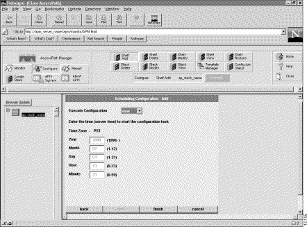
Scheduling the shelf configuration is the fifth and final step in either the Shelf Add or Shelf Modify procedure. (See Figure 4-6 and Table 4-9.)
| Step | Description |
|---|---|
| 1. Choose to execute the configuration Now or Later. | When doing a Shelf Add or Shelf Modify, you can have the configurations downloaded to the shelf now or later. |
| 2. (Required only if you selected Later in Step 1.) Enter the time on the server when the configuration task should start. | If you chose to download the configuration job later, use these fields to schedule the job. The download will occur when the server time matches the time you configure.
|
| 3. Click Finish. | Clicking Finish will start or schedule the downloading of the configuration file. |
 |
Tip |
1. Verify that any passwords you entered on the configuration screens are the correct ones for the shelf.
2. Verify that there is physical connectivity to the shelf.
3. Verify the IP address that you have configured for the configuration download by connecting to that port using Telnet. (You configured this IP address in Step 2 of Table 4-8.)
4. Try rescheduling the configuration. The console port might have been busy when APM attempted the download.
Use this procedure to view a shelf. You cannot use the Shelf View feature to change the value of any field. If you need to modify a shelf, see the section "Adding or Modifying a Shelf".
Step 2 Click Configure.
Step 3 Click Shelf View.
Step 4 Click Execute.
Step 5 Click Next to move through the screens. For an explanation of the data fields in these screens, refer to the section "Adding or Modifying a Shelf".
Use the following procedure to delete a shelf.
Step 2 Click Configure.
Step 3 Click Shelf Delete.
Step 4 Click Execute.
Step 5 Click Next to move through the four screens that show the configuration of the shelf you want to delete. For an explanation of the data fields in these screens, refer to "Adding or Modifying a Shelf".
Step 6 If this is the correct shelf, and you are sure you want to delete it and all of its historical data, click Delete. Otherwise, click Cancel.
Use the following Restore Shelf procedure if you have replaced a physical device and want to use an existing configuration for the new device:
Step 2 Click Configure.
Step 3 Click Shelf Restore.
Step 4 Click Execute.
Step 5 Enter a unique number in the Serial Number field in the General Information dialog box. Click Finish.
![]()
![]()
![]()
![]()
![]()
![]()
![]()
![]()
Posted: Tue Jan 21 04:20:27 PST 2003
All contents are Copyright © 1992--2002 Cisco Systems, Inc. All rights reserved.
Important Notices and Privacy Statement.