|
|

 | Warning The procedures listed in this chapter should be performed by qualified service personnel only. Always unplug the power cord before opening the chassis to avoid contact with dangerous voltages. |
This section describes procedures for adding random access memory (RAM) to your system by installing single in-line memory modules (SIMMs), and for upgrading the system software by replacing the erasable programmable read-only memory components (EPROMs) on the system card. These procedures must be performed by a qualified service technician; do not attempt these procedures unless you are trained to work on electrical equipment.
Detailed procedures, which are included with system software upgrade kits, also are included in this publication for reference. You can upgrade the 500-CS RAM with an upgrade kit ordered from Cisco Systems or with SIMMs from an approved source. This chapter provides a list of approved SIMM manufacturers and the procedure for installing SIMMs.
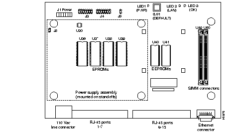
The system card, and the location of the major components and jumpers, are shown in Figure 4-1.
This section describes the procedure for opening the chassis to access the system card. Follow these steps when either adding RAM or upgrading the system software. The chassis should be opened only by a qualified service technician.
 | Warning Always unplug the power cord before opening the chassis. Removing the chassis cover exposes the power supply and dangerous voltages. |
Before beginning this procedure, review the safety procedures in Chapter 2 and read through the following procedures to ensure that you have all the tools and equipment you will need. To avoid having to leave the chassis open and unattended, allow enough time to complete the procedures.
You need the following tools when opening the chassis:
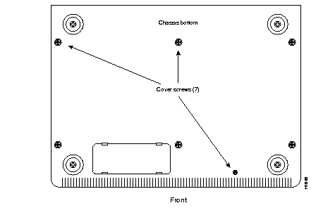
The chassis cover is secured by seven Phillips screws, which are recessed in the underside of the chassis (see Figure 4-2). Perform these steps over a cleared off bench or table so that you don't lose any screws when they drop out.
Step 1: Unplug the power cord from the wall receptacle.
Step 2: Turn the server upside down, with the rear of the chassis nearest you.
Step 3: Locate the seven recessed cover screws, shown in Figure 4-2.
Step 4: Loosen each of the screws about ten turns. The screws are tight; apply sufficient downward pressure on the screwdriver to avoid shearing the Phillips slots on the heads of the screws. Do not remove any screws until all seven are loose.
Step 5: When all the screws are loosened, unscrew them all the way from their sockets.
Step 6: Carefully turn the chassis right-side up. The screws will drop out of the recessed holes.
Step 7: Lift the top cover off the chassis and put it aside out of traffic areas.
When the new system card components are installed, follow the steps below to replace the cover.
 | Warning Replace the cover before plugging in the power cord to check the installation. When the cover is off the chassis, the power supply and dangerous voltages are exposed. |
Step 1: Place the cover back on the chassis and ensure that it is aligned properly.
Step 2: Turn the chassis over.
Step 3: For an installation check, replace at least two screws and tighten them about six turns.
Step 4: Turn the chassis right side up and gently try to lift the cover. If it comes off, turn the chassis over and tighten the screws a few more turns.
Step 5: When the cover is secure, plug in the power cord and power up the server for an installation check.
Step 6: When the installation tests successfully, unplug the power cord.
Step 7: Turn the chassis upside down, and replace and tighten the remaining screws.
Step 8: Turn the chassis over and plug in the power cord to resume operation.
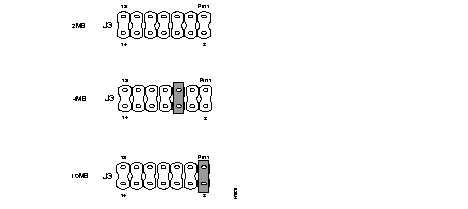
The 500-CS contains two megabytes of RAM permanently soldered onto the system card. The two RAM expansion sockets, U39 and U40 (see Figure 4-1), allow you upgrade your server RAM to four megabytes (by adding two 1-megabyte SIMMs) or to ten megabytes (by adding two 4-megabyte SIMMs). The two expansion slots must both be empty, or both be populated with SIMMs of the same size and speed. Each of the three options is illustrated in Figure 4-3. Memory upgrade kits are available from your local sales representative or customer service; refer to the "Service and Support" section in the front of this guide for ordering information.
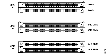
 | Caution The RAM expansion slots must both be empty or both contain SIMMs of identical size and speed, or the system will not operate. |
You can install SIMMs you obtain from a source other than Cisco Systems if the SIMMs have the following characteristics:
Table 4-1 provides a list of SIMMs (by supplier) that have been tested in the server and are known to be reliable.
| Size | Speed | Manufacturer | Part Number |
|---|---|---|---|
| 1M x 9 | 80 ns | Motorola | MCM91000-80 |
| 1M x 9 | 80 ns | Mitsubishi | MH1M09A0JA-80 |
| 1M x 9 | 80 ns | Toshiba | THM91000AS-80 |
| 1M x 9 | 80 ns | Texas Instruments | TM024EAD9-80L |
| 4M x 9 | 70 ns | Texas Instruments | TM4100EBD9-70 |
The following tools are required for this procedure:
You must have one of the following sets of parts:
You will install a new SIMM in each of the two RAM expansion slots shown in Figure 4-1. If the expansion slots in your server are empty (your system currently contains a total of 2 MB of RAM), skip the procedure "Removing Existing SIMMs" and proceed to "Installing New SIMMs" on page 4-8. Place removed SIMMs on an antistatic mat and store them in an antistatic bag (unless you are replacing a failed SIMM). The SIMMs can be reused in compatible equipment.
Follow this procedure only if you are replacing a failed SIMM card or if you are upgrading existing 1-MB SIMMs to 4-MB SIMMs.
Step 1: Unplug the chassis power cord and remove the chassis cover as described in "Opening the Chassis" on page 4-2.
Step 2: On the system card, locate RAM expansion slots U49 and U50 (see Figure 4-1). Both slots should contain a SIMM card.
Step 3: Turn the chassis so that the side with the RAM expansion slots is closest to you, and the slots are oriented horizontally (rotated 90 degrees clockwise from the orientation shown in Figure 4-1).
Step 4: Slip on an ESD wrist strap and ensure that it makes good contact with your skin. Connect the equipment end of the wrist strap to the metal back plate of the chassis, avoiding contact with the connectors.
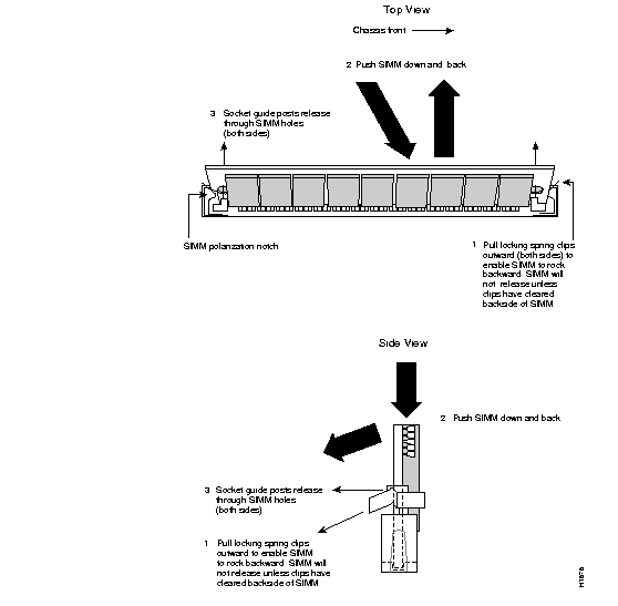
Step 5: Remove the SIMM from the back expansion slot (U49) first. The SIMMs are held in place by small metal spring tabs. Place your thumbs on the upper corners of the SIMM, as shown in Figure 4-4.
Step 6: Use your index fingers to push the metal tabs outward, while using your thumbs to push the SIMM back and downward about 45 degrees to release it from the metal tabs. See Figure 4-4.
 | Caution The SIMM requires firm pressure to release it; however, if you feel too much resistance, do not force the SIMM, or you might damage it. Look straight down on the SIMM as you push the metal tabs out; the side of the SIMM must clear the metal tab before it can be pushed back. |
Step 7: Hold the SIMM by the edges with your thumb and index finger, and it lift out of the slot. Place the removed SIMM in an antistatic bag to protect it from ESD damage.
Step 8: Repeat steps 5 through 7 for the SIMM in the front slot, U50.
Proceed to step 5 of the next procedure, "Installing New SIMMs."
 | Caution Handle SIMMs by the card edges only. SIMMs are sensitive components that can be shorted by mishandling. |
Follow this procedure to install new SIMMs in both RAM expansion slots.
Step 1: Unplug the chassis power cord and remove the chassis cover as described in "Opening the Chassis" on page 4-2.
Step 2: On the system card, locate RAM expansion slots U49 and U50 (see Figure 4-1). Both slots should be empty.
Step 3: Turn the chassis so that the side with the RAM expansion slots is closest to you, and the slots are oriented horizontally (rotated 90 degrees clockwise from the orientation shown in Figure 4-1).
Step 4: Slip on an ESD wrist strap, ensuring that it makes good contact with your skin. Connect the equipment end of the wrist strap to metal back plate of the chassis, avoiding contact with the connectors.
Step 5: Remove a new SIMM from the antistatic bag; handle it by the card edges.
 | Caution Handle SIMMs by the card edges only. SIMMs are sensitive components, and can be shorted by mishandling. |
Step 6: Hold the SIMM with the connector edge at the bottom and the component side facing you. SIMMs are manufactured with a polarization notch to prevent them from being installed backwards. Hold the SIMM with the polarization notch on the left, as shown in Figure 4-5.

.
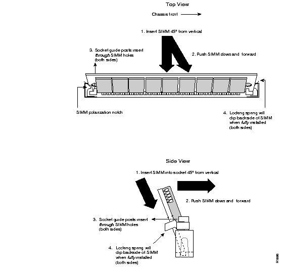
Step 7: Install the first SIMM in U50, the slot closest to you. Tilt the SIMM back at an angle of about 45 degrees from vertical, and slide the connector edge into the slot (see Figure 4-6).
Step 8: Gently push the SIMM into the slot at the same angle.
Step 9: When the edge is approximately 1/4 inch into the slot, place your index fingers on the side edges of the card and gently push it towards you. When the SIMM is perpendicular to the socket, the metal spring tabs on the slot will snap into the alignment holes on the SIMM. If the tabs do not snap into place, carefully rock the SIMM in the socket to seat it properly.
 | Caution If you feel resistance, do not force the SIMM, or you might damage the socket. The socket will have to be replaced if it breaks. Check the alignment of the SIMM to make sure it is straight (the top edge is parallel to the socket) and that the alignment holes are lined up with the plastic tabs on the socket (see Figure 4-5). |
When you add RAM to your system, you must also change a jumper setting on J3 for your server to recognize the new RAM size and operate properly. If you replaced a failed component and did not change the RAM amount, skip step 1.
Step 1: Locate jumper array J3, shown in Figure 4-1. Depending upon the amount of RAM now in your system, install a jumper as follows (see Figure 4-7 for jumper settings):
Step 2: You can now check out the installation; however you must replace the cover before powering up the system. Proceed to step 1 of "Replacing the Cover" on page 4-3.
 | Warning Always replace the chassis cover before plugging in the power cord. When the cover is off, the power supply and dangerous voltages are exposed. |
With the chassis cover on, power up the system and check the installation by observing the status indicators on the front panel and the display on any attached terminal. You may also use EXEC commands to display the current system configuration. In the following steps, common troubleshooting suggestions follow each step in the verification. If the system does not operate properly after troubleshooting, contact your service representative or the TAC at the number listed in the "Service and Support" section in the front of this publication.
Step 1: Plug the power cord into the AC outlet. The PWR indicator on the front panel should light and remain lit. If it does not light, do the following:
Step 2: Wait for the system to complete the boot process. This takes approximately one minute if your system has 2 MB of RAM, and up to 2 1/2 minutes if it has 10 MB.
Step 3: When the system has booted, the OK indicator also lights. If it does not, unplug the power cord and remove the cover to check the SIMMs and jumper settings.
Check the SIMMs by looking straight down on them and then at eye level. Make sure the tops of the SIMMs are straight (parallel with the socket and card) and the metal spring tabs are snapped into the alignment holes on the SIMMs. If either of the SIMMs appears misaligned, carefully remove it and reseat it in the socket. Replace the cover before plugging the power cord back in for another installation check.
Step 4: When the OK indicator lights, the message Press return to get started is displayed on all lines. If the message is not displayed, do the following:
Step 5: Enter the show version command on any terminal. The new amount of RAM is displayed on the eighth line along with the processor type.
When you enter the show version command, the display should look similar to the following:
CS Software (LCS-L), Version 9.1(1)
Copyright (c) 1986-1991 by cisco Systems, Inc.
Compiled Thu 01-Jun-92 19:04

System Bootstrap, Version 4.5(1)

organic uptime is 1 minute
System restarted by reload
Running default software
Cisco-500 (68331) processor with 4096K bytes of memory.
SuperLAT software (copyright 1990 by Meridian Technology Corp).
1 Ethernet/IEEE 802.3 interface.
16 terminal lines.
8K bytes of non-volatile configuration memory.
Configuration register is 0x2
Step 6: As activity on the network resumes, the LAN indicator flashes intermittently. If it does not light, and there are open connections to the server, do the following:
When the 500-CS boots successfully, replace and secure any remaining cover screws as described in "Replacing the Cover" on page 4-3.
The memory upgrade procedure is complete.
For descriptions of commands and instructions for setting up and making changes to the system configuration, refer to the Terminal Server Configuration and Reference Addendum for the Cisco 500-CS publication.
The system software is stored on two or four EPROMs, which are located in sockets U36, U37, U38, and U39 as shown in Figure 4-1. To upgrade the system software, you will replace all of these EPROMs. The new EPROMs may not be the same capacity as those you are replacing, so you might replace two existing EPROMs with four new ones, or four existing ones with two new ones. You might also need to change a jumper setting (jumper J3 specifies the EPROM size to the system software); specific instructions are included in the documentation that accompanies the upgrade kit. If your new software includes the LAT option, you will also replace the component in socket U22. Upgrade kits are available from your local sales representative or customer service; refer to the "Service and Support" section in the front of this publication for ordering information.
 | Warning Always unplug the power cord before opening the chassis. Removing the chassis cover exposes the power supply and dangerous voltages. |
The following tools are required for this procedure:
The following parts, which are required to upgrade the software, are included in the software upgrade kit:
If you are adding the LAT feature that previously did not have it, your upgrade kit will also contain the following parts.
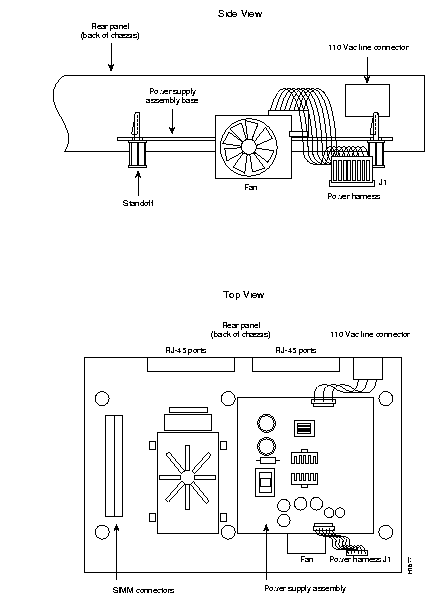
You must remove the power supply assembly to access the EPROMs. The power supply is mounted on a raised platform about two inches above the main circuit card, as shown in Figure 4-8. Perform the following steps to remove the power supply assembly.
Step 1: Unplug the chassis power cord and remove the chassis cover as described in "Opening the Chassis" on page 4-2.
Step 2: Turn the chassis so that the front (the edge with the LEDs) is closest to you, as shown in Figure 4-8).
Step 3: Slip on an ESD wrist strap and ensure that it makes good contact with your skin. Connect the equipment end of the wrist strap to the metal back plate of the chassis, avoiding contact with the connectors.
Step 4: On the system card, locate power connector J1 (shown in Figure 4-8). Disconnect the wiring harness connector at J1.
Step 5: The power supply assembly is mounted on four standoffs on the system card. The top of each standoff contains an expanding tab that snaps outward when it protrudes through the mounting hole on the power supply assembly base.
Step 6: Use needle-nosed pliers or a small screwdriver to push the tab inward while you slip the power supply assembly base over the tab (see Figure 4-9). Only lift the base up far enough to prevent the tab from snapping back into place; if you try to pull it completely off the standoff, you might damage the card or other standoffs.
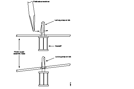
Step 7: Repeat step 6 for the other three standoffs, lifting up each corner of the base only far enough to clear the tab.
Step 8: When all four mounting holes are clear, carefully lift the power supply assembly off the standoffs and place it on an antistatic mat.
Once the power supply assembly is removed, the four EPROM sockets are easily accessible. All four EPROMs must be replaced to upgrade the software.
Step 1: You should still be wearing an ESD wrist strap, and the strap should be attached to the metal back panel of the chassis.
Step 2: On the system card, locate the EPROM sockets, U36, U37, U38, and U39 (shown in Figure 4-1). Depending upon the capacity of the EPROMs, either two or four may be present.
Step 3: Use a chip extractor to carefully remove all of the EPROMs from their sockets (two or four). If a chip extractor is not available, use the tip of a flat blade screwdriver to gently rock them out of the sockets. Place removed EPROMs on an antistatic mat or in an antistatic bag.
 | Caution When inserting the EPROMs, be careful not to bend or crush any of its pins. If this happens, use needle-nosed pliers to straighten the pin, then carefully reinsert it in the socket. |
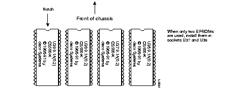
Step 4: Insert the new EPROMs; a label on each EPROM shows the correct socket, along with a byte designator label you can use to identify the correct socket (see Figure 4-10). If you are installing only two EPROMs, install them in sockets U37 and U38. When you insert each component, align the EPROM notch with the notch in the socket. Figure 4-10 illustrates the correct orientation of the EPROMs. The notched edge should be closest to the front of the chassis.
Steps 5 and 7 are only applicable if you are adding LAT to a system that previously did not have it.
Step 5: If your software upgrade includes the LAT option, your upgrade kit will include a replacement component for U20 (located near the EPROMs, as shown in Figure 4-1). Use a chip extractor to remove and replace the U22 component.
Step 6: Your upgrade kit also contains two labels with the new Ethernet address for your server. Place the new labels over the old ones. One label is located on the back of the server above the Ethernet connector, and the other label is on the underside of the chassis. Record the new address in your Site Log and any other site records.
Step 7: Depending upon the number and capacity of the new software EPROMs, you may need to change the setting of jumper J4. If so, detailed instructions are included with the installation instructions that accompany the upgrade kit. For reference, the settings of J4 for various EPROM sizes are provided in Table 4-2.
| Number of EPROMs | EPROM type | Total Capacity | Place jumper(s) on pins | ||
|---|---|---|---|---|---|
| 2 | 27C040 (512 K) | 1 MB | 9 & 10 | ||
| 2 | 27C080 (1 MB) | 2 MB | 9 & 10 | 11 & 12 | |
| 4 | 27C020 (256 KB) | 1 MB | 7 & 8 | 11 & 12 | |
| 4 | 27C040 (512 K) | 2 MB | 7 & 8 | 9 & 10 | |
| 4 | 27C080 (1 MB) | 4 MB | 7 & 8 | 9 & 10 | 11 & 12 |
When replacing the power supply assembly, be sure it is positioned correctly. The fan should be on the side of the assembly closest to the front of the chassis.
Step 1: Place the power supply assembly back on the four standoffs, ensuring that the mounting holes are positioned directly over the standoffs.
Step 2: Ensure that the assembly is in the correct position. The corner with the wire harness should be closest to the power socket J1 on the system card.
Step 3: Place your fingers on all four edges of the base and press down firmly until you hear all four plastic tabs snap open.
Step 4: Reconnect the wire harness connector to J1 on the system card.
Step 5: You can now check out the installation; however, you must replace the cover before powering up the system. Refer to "Replacing the Cover" on page 4-3.
 | Warning Always replace the chassis cover before plugging in the power cord. When the cover is off, the power supply and dangerous voltages are exposed. |
With the chassis cover on, power up the system and check the installation by observing the status indicators on the front panel and the screen of an attached terminal. You can also use EXEC commands to display the current system configuration. In this section, common troubleshooting suggestions follow each step in the verification. If the system does not operate properly after troubleshooting, contact your service representative or the TAC at the number listed in the "Service and Support" section in the front of this publication.
Step 1: Plug the power cord into the AC outlet. The PWR indicator on the front panel should light and remain lit. If it does not light, do the following:
Step 2: Wait for the system to complete the boot process. This takes approximately one minute if your system has 2 MB of RAM and up to 2 1/2 minutes if it has 10 MB.
Step 3: When the system has booted, verify that the OK indicator lights. If any of the EPROMs is incorrectly inserted, the system will halt operation. If this happens, or if the OK indicator does not light, try the following:
Step 4: When the OK indicator lights, enter the show version command on any terminal connected to the 500-CS and ensure that it displays a banner similar to the following:
Step 5: If the terminal does not display a banner, do the following:
Step 6: As activity on the network resumes, the LAN indicator flashes intermittently. If it does not light, and there are open connections to the server, do the following:
Step 7: At the system prompt, enter the command show version. The first few lines of the screen display should be similar to the example in step 4. On the first line, the Version displayed should be that of the new software you just installed.
When the 500-CS boots successfully, replace any remaining cover screws as described in "Replacing the Cover" on page 4-3.
The software upgrade procedure is complete. Refer to the Terminal Server Configuration and Reference Addendum for the Cisco 500-CS publication for descriptions of commands and instructions for changing the system configuration.
|
|