|
|

Table Of Contents
Preparing to Install the Universal Access Server
Maintaining Safety with Electricity
Preventing Electrostatic Discharge Damage
Preparing to Connect to a Network
Synchronous Serial Connections
Speed and Distance Limitations
Console and Auxiliary Port Considerations
Preparing to Install the Universal Access Server
This chapter describes the tasks you must perform before you begin to install the access server and includes the following sections:
•
Preparing to Connect to a Network
Safety Recommendations
Maintaining Safety with Electricity
Follow these guidelines when you work on equipment powered by electricity.
Follow these guidelines when working on equipment powered by electricity:
•
•
— Installing or removing a chassis— Working near power supplies•
•
•
•
— Use caution; do not become a victim yourself.— Turn OFF power to the system.— If possible, send another person to get medical aid. Otherwise, determine the condition of the victim and then call for help.— Determine if the victim needs rescue breathing or external cardiac compressions; then take appropriate action.Preventing Electrostatic Discharge Damage
Electrostatic discharge (ESD) can damage equipment and impair electrical circuitry. ESD damage occurs when electronic components are improperly handled and can result in complete or intermittent failures.
Always follow ESD-prevention procedures when you remove and replace components. Ensure that the chassis is electrically connected to earth ground. Wear an ESD-preventive wrist strap, ensuring that it makes good skin contact. Connect the grounding clip to an unpainted surface of the chassis frame to safely ground unwanted ESD voltages. To guard against ESD damage and shocks, the wrist strap and cord must operate properly. If no wrist strap is available, ground yourself by touching the metal part of the chassis.
CautionFor safety, periodically check the resistance value of the antistatic strap, which should be between 1 and 10 megohm (Mohm).
General Site Requirements
This section describes the requirements your site must meet for safe installation and operation of your access server. Ensure that your site is properly prepared before beginning installation.
Site Environment
The access server can be placed on a desktop or mounted in a rack. The location of the access server and the layout of your equipment rack or wiring room are extremely important for proper system operation. Equipment placed too close together, inadequate ventilation, and inaccessible panels can cause malfunctions and shutdowns and make maintenance difficult.
When planning your site layout and equipment locations, keep in mind the precautions described in the next section, " Preventive Site Configuration," to help avoid equipment failures and reduce the possibility of environmentally caused shutdowns. If you are currently experiencing shutdowns or an unusually high number of errors with your existing equipment, these precautions might help you isolate the cause of failures and prevent future problems.
Preventive Site Configuration
The following precautions can help you plan an acceptable operating environment for your access server and will help you avoid environmentally caused equipment failures:
•
•
•
Configuring Equipment Racks
The following tips will help you plan an acceptable equipment rack configuration:
•
•
•
•
Power Supply Considerations
Check the power at your site to ensure that you are receiving "clean" power (free of spikes and noise). Install a power conditioner if necessary.
Warning
The device is designed to work with TN power systems.
The AC power supply includes the following features:
•
•
Warning
This product relies on the building's installation for short-circuit (overcurrent) protection. Ensure that a fuse or circuit breaker no larger than 120 VAC, 15A U.S. (240 VAC, 10A international) is used on the phase conductors (all current-carrying conductors).
Preparing to Connect to a Network
When you set up your access server, consider distance limitations and potential electromagnetic interference (EMI) as defined by the Electronic Industries Association (EIA).
Warning
The ISDN connection is regarded as a source of voltage that should be inaccessible to user contact. Do not attempt to tamper with or open any public telephone operator (PTO)-provided equipment or connection hardware. Any hardwired connection (other than by a nonremovable, connect-one-time-only plug) must be made only by PTO staff or suitably trained engineers.
Warning
To avoid electric shock, do not connect safety extra-low voltage (SELV) circuits to telephone-network voltage (TNV) circuits. LAN ports contain SELV circuits, and WAN ports contain TNV circuits. Some LAN and WAN ports both use RJ-45 connectors. Use caution when connecting cables.
Warning
Hazardous network voltages are present in WAN ports regardless of whether power to the router is OFF or ON. To avoid electric shock, use caution when working near WAN ports. When detaching cables, detach the end away from the router first.
Dual T1/PRI Card
The dual T1/PRI card includes two RJ-48C ports. Cables specifications and port pinouts are listed in the section " Dual T1/PRI Card Port Pinouts" in the appendix " ."
lists the network specifications you should consider before connecting the dual T1/PRI card to a network.
Table 2-1
Line rate
1.544 Mbps
Data rates
number x 56 or number x 64 kbps, where number = 1 to 24
Standards
AT&T Pub. 62411, 54016, and 43801
ANSI T1.403
Dual T1/PRI Card Network Specifications
Warning
Network hazardous voltages are present in the T1/PRI cable. If you detach the cable, detach the end away from the access server first to avoid possible electric shock. Network hazardous voltages are also present in the area of the T1/PRI (RJ-48C) ports, regardless of whether power is OFF or ON.
Dual E1/PRI Card
The dual E1/PRI card includes two DB-15 ports for terminating 120-ohm balanced lines or 75-ohm unbalanced lines. Jumper settings on the card configure the ports for the line termination. Jumper positions and settings are listed in the section " Setting E1 Port Jumpers" in the appendix " ."
Cable specifications and port pinouts are listed in the section" Dual E1 or T1/PRI Card Cable Assemblies and Pinouts" in the appendix " ."
Warning
Network hazardous voltages are present in the E1/PRI cable. If you detach the cable, detach the end away from the access server first to avoid possible electric shock. Network hazardous voltages are also present in the area of the E1/PRI (DB-15) ports, regardless of whether power is OFF or ON.
Synchronous Serial Connections
Before you connect a device to the synchronous serial port (labeled Serial), you will need to know the following:
•
•
•
DTE or DCE
A device that communicates over a synchronous serial interface is either a DTE or DCE device. A DCE device provides a clock signal that paces the communications between the device and the access server. A DTE device does not provide a clock signal. DTE devices usually connect to DCE devices. The documentation that came with the device should indicate whether it is a DTE or DCE device. (Some devices have a jumper to select either type.) If you cannot find the information in the documentation, refer to to help you select the proper device type.
Table 2-2 Typical DTE and DCE Devices
DTE
Male1
Terminal
PC
Access server or router
DCE
Female2
Modem
CSU/DSU3
Multiplexer
1 If pins protrude from the base of the connector, the connector is male.
2 If the connector has holes to accept pins, the connector is female.
3 CSU/DSU = channel service unit/data service unit.
Speed and Distance Limitations
Serial signals can travel a limited distance at any given bit rate; generally, the slower the data rate, the greater the distance. All serial signals are subject to distance limits, beyond which a signal degrades significantly or is completely lost.
lists the maximum speeds and distances for EIA/TIA-232 signals. This signaling standard supports unbalanced circuits at signal speeds up to 64 kbps.
Table 2-3 EIA/TIA-232 Speed and Distance Limitations
2400
200
60
4800
100
30
9600
50
15
19200
50
15
38400
50
15
64000
25
7.6
Balanced drivers allow EIA/TIA-449 signals to travel greater distances than the EIA/TIA-232 signals. lists the maximum speeds and distances for EIA/TIA-449, V.35, X.21, and EIA-530 signals.
CautionThe EIA/TIA-449 and V.35 interfaces support data rates up to 2.048 Mbps. Exceeding this maximum could result in loss of data and is not recommended.
Signaling Standards
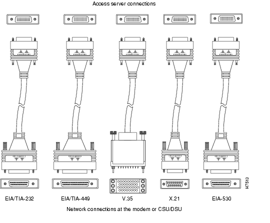
The synchronous serial port supports the following signaling standards: EIA/TIA-232, EIA/TIA-449, V.35, X.21, and EIA-530. You can order a DB-60 shielded serial transition cable that has the appropriate connector for the standard you specify. The access server end of the shielded serial transition cable has a DB-60 connector, which connects to the serial port on the rear panel of the access server. The other end of the serial transition cable is available with the connector appropriate for the standard you specify. The documentation for the device you want to connect should indicate the standard used for that device. The synchronous serial port can be configured as DTE or DCE (except EIA-530, which is DTE only), depending on the attached cable.
Note
shows the serial transition cables you can connect to the serial port on the rear panel of the access server.
Figure 2-1 Serial Transition Cables
Although attempting to manufacture your own serial cables is not recommended (because of the small size of the pins on the DB-60 serial connector), cable pinouts are provided in the appendix " ." For ordering information, refer to the section " Getting Help" in the appendix " ."
EIA/TIA-232 Connections
The EIA/TIA-232 standard supports unbalanced circuits at signal speeds up to 64 kbps. The serial port (labeled Serial) supports synchronous connections. The console and auxiliary ports also use an EIA/TIA-232 connection; however, the console and auxiliary ports support asynchronous connections.
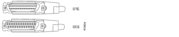
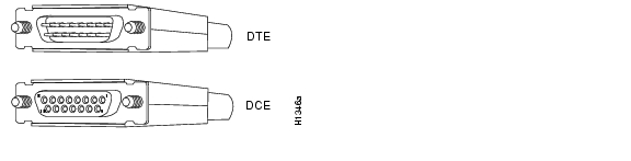
The network end of the EIA/TIA-232 serial transition cable (not included) provides a DB-25 connector, as shown in . The end that connects to the serial port on the rear panel of the access server has a DB-60 connector. EIA/TIA-232 serial transition cables are available with a DB-25 plug or receptacle in either DTE or DCE mode.
Figure 2-2 EIA/TIA-232 Serial Transition Cable Connectors, Network End
EIA/TIA-449 Connections
The EIA/TIA-449 standard, which supports balanced and unbalanced transmissions, is a faster (up to 2 Mbps) version of the EIA/TIA-232 standard that provides more functions and supports transmissions over greater distances.
The EIA/TIA-449 standard was intended to replace the EIA/TIA-232 standard, but it was not widely adopted primarily because of the large installed base of DB-25 hardware and because of the larger size of the 37-pin EIA/TIA-449 connectors, which limited the number of connections possible (fewer than possible with the smaller, 25-pin EIA/TIA-232 connector).
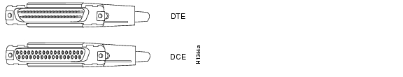
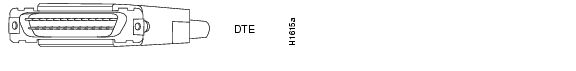
The network end of the EIA/TIA-449 serial transition cable (not included) provides a DB-37 connector, as shown in . The end that connects to the serial port on the rear panel of the access server has a DB-60 connector. EIA/TIA-449 serial transition cables are available with a DB-37 plug or receptacle in either DTE or DCE mode.
Figure 2-3 EIA/TIA-449 Serial Transition Cable Connectors, Network End
V.35 Connections
The V.35 standard is recommended for speeds up to 48 kbps, although in practice it is used successfully at 4 Mbps.
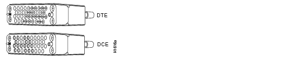
The network end of the V.35 serial transition cable (not included) provides a standard 34-pin Winchester-type connector, as shown in . The end that connects to the serial port on the rear panel of the access server has a DB-60 connector. V.35 cables are available with a standard V.35 plug or receptacle in either DTE or DCE mode.
Figure 2-4 V.35 Serial Transition Cable Connectors, Network End
X.21 Connections
The X.21 connector uses a 15-pin connector for balanced circuits and is commonly used in the United Kingdom to connect to the public data network. X.21 relocates some of the logic functions to the DTE and DCE interfaces and, as a result, requires fewer circuits and a smaller connector than EIA/TIA-232.
The network end of the X.21 serial transition cable (not included) is a standard DB-15 connector, as shown in . The end that connects to the serial port on the rear panel of the access server has a DB-60 connector. X.21 cables are available with a plug or receptacle in either DTE or DCE mode.
Figure 2-5 X.21 Serial Transition Cable Connectors, Network End
EIA-530 Connections
The EIA-530 standard, which supports balanced transmission, provides the increased functionality, speed, and distance of EIA/TIA-449 on the smaller, DB-25 connector used for EIA/TIA-232, instead of the 37-pin connector used for EIA/TIA-449. Like EIA-TIA-449, EIA-530 refers to the electrical specifications of EIA/TIA-422 and EIA/TIA-423. Although the specification recommends a maximum speed of 2 Mbps, EIA-530 is used successfully at 4 Mbps or faster speeds over short distances.
The EIA/530 serial transition cable (not included) is available in DTE mode only. The network end of the EIA-530 adapter cable is a standard DB-25 plug commonly used for EIA/TIA-232 connections, as shown in . The end that connects to the serial port on the rear panel of the access server has a DB-60 connector.
Figure 2-6 EIA-530 Serial Transition Cable Connector, Network End
Ethernet Connections
The IEEE has established Ethernet as standard 802.3. The most common Ethernet implementations are as follows:
•
•
•
The access server includes one Ethernet attachment unit interface (AUI) interface, which operates at speeds up to 10 Mbps.
The cables and transceivers required to connect the access server to an Ethernet network are not included.
Console and Auxiliary Port Considerations
The access server includes an asynchronous serial console and auxiliary port. The console and auxiliary ports provide access to the access server either locally (with a console terminal) or remotely (with a modem). This section discusses important cabling information to consider before connecting a console terminal (an ASCII terminal or PC running terminal emulation software) to the console port or modem to the auxiliary port.
The main difference between the console and auxiliary ports is that the auxiliary port supports hardware (RTS/CTS) flow control and the console port does not. Flow control paces the transmission of data between a sending device and a receiving device. Flow control ensures that the receiving device can absorb the data sent to it before the sending device sends more. When the buffers on the receiving device are full, a message is sent to the sending device to suspend transmission until the data in the buffers has been processed. Because the auxiliary port supports flow control, it is ideally suited for use with the high-speed transmissions of a modem. Console terminals transmit at slower speeds than modems; therefore, the console port is ideally suited for use with console terminals.
Console Port Connections
The access server includes an EIA/TIA-232 asynchronous serial console port (RJ-45). Depending on the cable and the adapter used, this port will appear as a DTE or DCE device at the end of the cable. Your access server comes with cables and adapters to connect a console terminal (an ASCII terminal or PC running terminal emulation software) to the console port. To connect an ASCII terminal to the console port, use the RJ-45-to-RJ-45 rollover cable with the female RJ-45-to-DB-25 adapter (labeled Terminal). To connect a PC running terminal emulation software to the console port, use the RJ-45-to-RJ-45 rollover cable with the female RJ-45-to-DB-9 adapter (labeled Terminal). The default parameters for the console port are 9600 baud, 8 data bits, no parity, and 2 stop bits. The console port does not support hardware flow control. For detailed information about installing a console terminal, see the section " Connecting the Console Terminal and Modem" in the chapter " ." See the appendix " " for cable and port pinouts.
Auxiliary Port Connections
The access server includes an EIA/TIA-232 asynchronous serial auxiliary port (RJ-45) that supports flow control. Depending on the cable and the adapter used, this port will appear as a DTE or DCE device at the end of the cable. Your access server comes with a cable and an adapter to connect a modem to the auxiliary port. To connect a modem to the auxiliary port, use the RJ-45-to-RJ-45 rollover cable with the male RJ-45-to-DB-25 adapter (labeled Modem). For detailed information about connecting devices to the auxiliary port, see the section " Connecting a Modem to the Auxiliary Port" in the chapter " ." See the appendix " " for cable and port pinouts.
Alarm Port Connections
The 3-pin alarm port connects the access server to an external audio, visual, or other type of alarm.
Note that the alarm port is not currently operable. When software to operate the port becomes available, use 22 AWG, or thicker, copper wires to connect to the alarm port terminal blocks.
Note
![]()
![]()
![]()
![]()
![]()
![]()
![]()
![]()
Posted: Tue May 4 18:39:52 PDT 2004
All contents are Copyright © 1992--2004 Cisco Systems, Inc. All rights reserved.
Important Notices and Privacy Statement.