|
|

Product Numbers: MAS-MSA= and MAS-MSB=
This document discusses the field installation of the optional MAS-MSA and MAS-MSB slide-mount kits on the M chassis.
 | Caution Before beginning this procedure, review the entire document. If you have any doubts about your ability to perform any part of this installation procedure, contact a service representative for information on how to proceed. |
The replacement parts for this document are the MAS-MSA and MAS-MSB slide-mount kits. The kits can only be used on the M chassis and are only available as optional equipment. The kits allow you to install the M chassis in a standard 19'' wide equipment rack and expose the chassis access panel (located on the side of the chassis) by attaching one telescoping slide to each side of the chassis. These slides allow you to expose the panel by pulling the chassis out of the rack, much like pulling out a drawer, and then removing the panel to access the cards in the card cage.
The length of the MAS-MSA slides adjusts from 20'' to 24'', while the MAS-MSB slides adjust from 20'' to 34''. The rack brackets that attach to the ends of the slides provide this adjustment and allow the assemblies to accommodate most available rack depths.
The final task in this installation procedure may require two people because it is necessary to support the chassis (with the slides attached) as it is installed in the equipment rack.
Refer to the following procedures and accompanying illustrations for installing the MAS-MSA and MAS-MSB slide-mount kits.
The following tools and parts are required for installing the slide-mount kit.
Following is the procedure for attaching the slide assemblies.
Step 1: If the chassis is currently mounted in an equipment rack, remove all external cables and the chassis (from the rack), and place it on a work table. Note or label the position of each external cable for chassis reinstallation.
Step 2: Remove the slide-mount kit from its packaging and inventory the hardware included with the kit (see the list of parts on the previous page).
Step 3: Examine one of the slide assemblies.
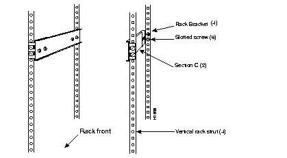
Observe that the slide has three distinct sections. Figure 1 shows how the slide assemblies look when attached to the vertical rack struts.
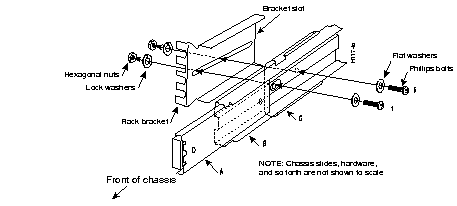
The inner, thinnest section (section A) fits inside the other two sections (sections B and C respectively--see Figure 2) creating a telescoping effect. It is section A that is attached to the chassis side (see Figure 3 or Figure 4). The rack brackets are bolted to the ends of each slide, wrapping around the edges of section C (the outer or widest section of the slide).

Step 4: Refer to Figure 2 and orient the front end of the left-side slide assembly by pulling sections A and B until they are fully extended from section C. In this position, the oval hole in section B and the round screw hole in section C are aligned as they appear in Figure 2.

Step 5: With sections A and B fully extended to the left (in the direction of the front of chassis orientation shown in Figure 2), insert bolt 1 through the following: the flat washer, the oval hole in section B, the round screw hole in section C, and the bracket slot as shown in Figure 2. Attach the lock washer and nut to bolt 1.
Step 6: Tighten the nut and bolt snugly; do not overtighten.
Step 7: Slide section B to the right (approximately 1 inch) and align the oval hole with the second round screw hole (shown in Figure 2 as a dotted circle) in section C.
Step 8: Insert bolt 2 through the following: the flat washer, the oval hole in section B, the round screw hole in section C, and the bracket slot as shown in Figure 2. Attach the lock washer and nut to bolt 2.
Step 9: Tighten the nut and bolt snugly; do not overtighten.
Step 10: The second rack bracket at the rear of the slide can now be attached to section C, with the nuts, bolts, washers, and slide positioned as shown in Figure 2.
 | Caution Keep the nuts and bolts in the rear bracket loose. Do not tighten the nuts and bolts in the rear bracket because this bracket will be used for length adjustments in the following section. |
Step 11: Repeat steps 4 through 10 for the right-side slide assembly.
Following is the procedure for adjusting the length of the slide assemblies.
Step 1: Using the large slotted screws, attach the slide assemblies to the rack struts as shown in Figure 1, and adjust the rear brackets between the rack struts.
Step 2: Determine the exact distance between the front and rear rack struts and tighten the nuts and bolts in the rear rack brackets; do not overtighten.
Step 3: Remove the sized slide assemblies from the rack struts and prepare to attach them to the chassis sides.
 | Caution The three access panel screws may not be accessible when the chassis is slide mounted. Before you attach the slide assemblies to the chassis sides, loosen (but do no remove) the three Phillips access panel screws located along the bottom edge of the access panel on the side of the chassis (shown in Figure 3 and Figure 4). |
Following is the procedure for installing the MAS-MSA short-slide assemblies. If you are installing the MAS-MSB, proceed to the following section, "Attaching the MAS-MSB Slides to the Chassis."
Step 1: Refer to Figure 3 and attach the slide assemblies to the sides of the chassis. Start with the right-side assembly. The first and second screws (inserted in the second and third chassis screw holes from the chassis front) are easy to attach, but the two screws toward the rear of the chassis require aligning the oval hole (in section B of the slide) with the screw holes in section A. To do this alignment, slide section B over section A to expose these two screw holes.

Step 2: Use four of the Phillips screws (with washers included) to attach one slide to each chassis side. Refer to Figure 3 for the correct alignment between the screw holes on the slide (section A) and the screw holes on the chassis side.
Step 3: To attach the left-side slide assembly, repeat steps 1 and 2.
Proceed to the section "Installing the Entire Assembly in the Equipment Rack."
Following is the procedure for installing the MAS-MSB long-slide assemblies.
Step 1: Refer to Figure 4 and attach the slide assemblies to the side of the chassis. Start with the right-side assembly. The first screw (toward the chassis front--the second chassis screw hole) is easy to attach, but the second screw (toward the middle of the chassis--the fourth chassis screw hole) requires aligning the oval hole in section B with the screw hole in section A (see Figure 4). To do this alignment, slide section B over section A to expose the hole in section A.

Step 2: Use two of the Phillips screws (with washers included) to attach one slide to each chassis side. Refer to Figure 4 for the correct alignment between the screw holes on the slide (section A) and the screw holes on the chassis side.
Step 3: To attach the left-side slide assembly, repeat steps 1 and 2.
Proceed to the section "Installing the Entire Assembly in the Equipment Rack."
Following is the procedure for installing the chassis (with slide assemblies attached) in the equipment rack.
 | Caution This procedure requires two people: one to hold the chassis and the other to attach the screws through the rack brackets on the slide assemblies. The chassis assembly is heavy with the slide assemblies attached, and it may be awkward and dangerous for only one person to attempt. |
 | Time Saver In step 2, use one large slotted screw per rack bracket to temporarily support the weight of the chassis and reduce the time required for the second person. Attach the second screw to each rack bracket after the first four screws are installed. |
Step 1: Position the chassis in the rack so that the rack brackets align with the screw holes on the rack struts (see Figure 5).

Step 2: Attach at least one large slotted screw (per rack bracket) to each rack strut.
 | Caution Do not connect external cables to the chassis until after the installation is checked in the following section. |
You will now be able to pull the chassis out from the front of the equipment rack (see Figure 6). In future you will either need to disconnect all external cables or allow enough slack in these cables to accommodate the forward movement of the chassis.

Typically, the slides will only be used when the chassis requires some maintenance (requiring access to the chassis interior). If this occurs, the external cables should be disconnected, especially the power cable. You should also be able to remove the chassis access panel by turning the three slotted screws (located along the top edge of the side access panel) one-quarter turn to the left. These screws cannot be removed (see Figure 6).
 | Caution To prevent damage to the system cards and problems on the network, verify all of the external cable connections before applying power to the chassis. |
The chassis is now ready to be connected to the network.
|
|