|
|

Product Number: MAS-28M= and MAS-28C=
The primary replacement part for this procedure is the MAS-28 175 watt power supply, and is recommended for use in M and C chassis currently using the MAS-23 power supply. You must determine the power supply you have and use the appropriate documentation for that power supply.
| Caution This procedure is recommended only for experienced technicians and engineers because access to the chassis interior is required. Before beginning this procedure, it is strongly advised that you read through the entire document. If you have any doubts about your ability to perform any part of this procedure, contact a service representative for further guidance. |
| Warning Before accessing the chassis interior and removing any cards, turn off power to the chassis and unplug the power cord. Use extreme caution around the chassis since potentially harmful voltages are present. |
The MAS-28 will operate with either 110 volt or 220 volt alternating current (AC) source input (auto-ranging) and provides direct current (DC) output voltages of ± 5 volts and ± 12 volts.
Note: The kit you received includes the MAS-28, a new switch assembly, and assorted components and hardware. For this procedure, you will use the MAS-28 power supply and mounting plate and the 4A fuse located in the new switch assembly. For your new MAS-28 power supply to operate properly, the fuse in your M or C chassis must be replaced with the 4A fuse included in the new switch assembly.
Electrostatic discharge damage (ESD) occurs when electronic printed circuit cards are improperly handled and can result in complete or intermittent failures. ESD can impair electronic circuitry and equipment. Always follow ESD prevention procedures when removing and replacing cards.
Following are steps for handling printed circuit cards:
Step 2: Connect the strap to an unpainted chassis frame surface or another proper grounding point or surface to safely channel unwanted ESD voltages to ground.
Step 3: Use the ejectors to remove the card. Handle the card by its sides. Place the card on an antistatic surface or in a static shielding bag. To prevent further damage to the card by ESD voltages, defective cards must remain in the static shielding bag when returned to for repair or replacement.
Step 4: Handling the new card by its edges only, insert it into the chassis. Avoid contact between the card and clothing. The wrist strap only protects the card from ESD voltages on the body; ESD voltages on clothing can still damage the card.
Use an ohmmeter to check the ESD wrist strap to ensure that the resistor is providing proper ESD protection. For safety, the measurement should be in the range 1 to 10 Mohms.
Refer to the following procedures and accompanying illustrations to access and remove the MAS-23 power supply and to install the new MAS-28 power supply. Before you start any procedures, read through this entire document to familiarize yourself with the required tasks.
| Warning Before accessing the chassis interior and removing any cards, turn off power to the chassis and unplug the power cord. High voltages may exist in or near the power supply. Use extreme caution when working with the power supply. Attach appropriate ESD protection before beginning this procedure. |
Once you have taken the necessary ESD precautions, you can proceed with this upgrade procedure.
The following items are required for upgrading the MAS-23 power supply to the MAS-28 power supply:
n Two Phillips screwdrivers, No.1 and 2
n One medium-sized flat-blade screwdriver
n One pair of medium size needle nose pliers
n Digital Multimeter (DMM) or Digital Voltmeter (DVM)
Note: The following procedures differ for M and C chassis; refer to the appropriate section depending upon your chassis type.
Following is the procedure for accessing the M chassis:
Step 2: Locate the three screws that secure the card cage access panel. Use the flat-blade screwdriver to turn each of these screws 1/4 to 1/2 turn counterclockwise until the screws pop up.
Step 3: Loosen the three screws at the bottom edge of the card cage cover (do not remove these screws completely). Carefully remove the cover and set it aside.
Step 4: Orient the chassis so that the back (the side with the ports) is to your left; the front of the chassis (the side with the LED) is to your right; and the card cage opening is on the side of the chassis facing away from you. This will place the power supply on the side of the chassis closest to you. Looking straight down at the power supply, the position of the terminal strips and wires attached to them should resemble the wiring diagram in Figure 4.
Proceed to "Removing the MAS-23 Power Supply."
Following is the procedure for accessing the C chassis:
Step 2: Orient the chassis so that the back (the side with the ports) is on your left, and the front (with the LED) of the chassis is on your right. This will place the power supply on the side of the chassis closest to you after you remove the cover.
Step 3: Pull the front of the cover to the right while securing the back of the chassis with your left hand. Pull slowly and carefully; the fit is snug.
| Caution Several cables are located close to the interior of the C chassis cover. Avoid damage to these cables by ensuring that they do not impede the cover as you remove it. |
Step 4: Pull the cover to the right until the power supply and the card cage are completely exposed, but do not pull the cover completely off.
Step 5: Looking straight down at the power supply, the position of the terminal strips will resemble the wiring diagram in Figure 4.
Proceed to "Removing the MAS-23 Power Supply."
Following is the procedure for removing the MAS-23 power supply from both the M and C chassis:
Step 2: Use the No. 2 Phillips screwdriver to remove the screws located in the four corners and in the center of the MAS-23 power supply.
Note: Access to the center screw position may be partially blocked by wires (two black and one white) attached to the transformer.
Step 3: Carefully lift the right side of the power supply to gain access to the right-side terminal strip (J2). Use the flat-blade screwdriver to loosen (but not remove) the eight screws on J2 (see Figure 3) to which wires are attached (terminal positions 1 through 4 and 6 through 9). Pull the wires from beneath the screws.
Step 4: Carefully lift the left side of the power supply to gain access to the left-side terminal strip (J1). Use the flat-blade screwdriver to loosen (but not remove) all the screws on J1. Pull the wires from beneath the screws.
Step 5: Lift the power supply out of the chassis and set it aside. and ocate the power supply mounting plate attached to the chassis base.
Step 6: Remove the four screws securing this plate and set the screws and the plate aside.
Following is the procedure for installing the MAS-28 power supply:
Step 2: Use the flat-blade screwdriver to loosen all of the screws on terminal strips TB1 and TB2 (to which wires will be attached).
Step 3: Place the new power supply in the chassis. Refer to Figure 4 for correct positioning.
Step 4: Use the No. 2 Phillips screwdriver to reinstall the screws that secure the power supply mounting plate (attached to the MAS-28) to the chassis base.
Note: In the M chassis, five screws are used to secure the mounting plate and in the C chassis, four screws are used (the lower right screw hole shown in Figure 4 is not used in the C chassis).
Step 5: Locate the red and black wires from the backplane, noting that there are four red and four black wires. Two of each of these colors are shorter than the other two.
Step 6: Group the two short red wires together and then group the two long red wires.
Step 7: Group the two short black wires together.
Note: These three wire pairs will be attached to specific terminal positions in the following steps.
Step 8: Starting with terminal position TB2-1, attach the wires to TB2 (follow the wiring diagram in Figure 4). Make certain to attach the wire pairs to TB2-7 through TB2-9 (see Table 1) and the long chassis ground wire (green with yellow stripes) to TB2-5.
Table 1 Connections to Terminal TB2
|
|
Step 9: When all wires are secure, double check the color-coding for the wires in Figure 4 and Table 1.
Step 10: Follow the wiring diagram in Figure 4 to attach and secure the three wires to TB1 starting with TB1-1 (Line, brown wire).
Step 11: When all three wires are secure, double check the color-coding in Figure 4.
| Caution For the MAS-28 power supply to operate properly, the fuse must be replaced with the 4A fuse in the new switch assembly that was shipped with the power supply kit. It is not necessary to replace the entire switch assembly. |
Proceed to the section, "Replacing the Fuse in the Switch Assembly."
Following is the procedure for replacing the fuse in your chassis.
Step 2: Referring to Figure 5, Part A and B, use the medium flat-blade screwdriver to open the fuse-access doors on both the new switch assembly and on the switch in your chassis.
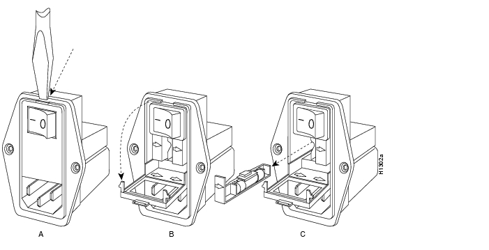
Step 3: Remove a fuse holder (there are two) from the new switch and remove the 4A fuse from the holder (see Figure 5, Part C).
Step 4: Remove the fuse holder from your chassis switch and remove the fuse from the holder (see Figure 5). Throw the old fuse away to avoid confusing it with the new one.
Step 5: Install the 4A fuse in your fuse holder, reinsert the fuse holder in your switch, and close the fuse-access door.
Step 6: Save the second 4A fuse in the new switch assembly as a spare.
Proceed to the section, "Testing the MAS-28 Power Supply."
After you install the new MAS-28 power supply in your chassis, you can test the installation by measuring the voltages on the new power supply. Testing will first be done with all cards removed from the chassis, and then with one card installed in the chassis. Testing with all cards removed will prevent damage caused by improper power supply wiring.
| Warning High voltages may exist in or near the power supply; use extreme caution when working with the power supply. Connect all ESD protection before proceeding. |
Following is the procedure for testing the new power supply in the M and C chassis:
Step 2: C chassis only—Locate the two clamps that hold the printed circuit cards in place in the card cage (see Figure 6) and use the flat-blade screwdriver to loosen the screws on the two clamps. Remove these clamps and set them aside.
Step 3: Locate the edge ejectors on the cards inside the card cage (see Figure 7). Partially remove all cards so that they make no electrical contact with the backplane. Do not remove the cards completely from the card cage. Follow the card removal procedures described earlier.
| Caution To avoid overheating the chassis during the following steps, apply power to the chassis only long enough to check the fan and LED operation. |
Step 4: Plug in the power cord and turn on power to the chassis. You are operating the power supply with no cards installed to protect them from damage due to an improperly wired power supply.
Step 5: Observe that the chassis fan(s) is (are) operating, which will indicate that the + 12 volt power supply is operational. Also check that the LED on the front panel of the chassis is on, indicating that the +5 volt power supply is operational.
Note: If the front-panel LED flickers, this is a typical condition with no load applied and does not indicate a failure in the power supply.
Step 6: Turn off power to the chassis and unplug the power cord.
Step 7: Re-insert only the processor card (in the top chassis slot) making certain it is properly seated. This card will provide a load to the power supply.
| Caution To avoid overheating the chassis during the following steps, apply power to the chassis only long enough to check the power supply voltages. |
Step 8: Plug in the power cord and turn on power to the chassis.
| Warning To avoid a short circuit and electrical shock hazard, exercise great care with the DMM probes. Do not touch more than one wire with one probe. A short circuit could cause damage to all cards and the power supply. |
Step 9: Referring to Figure 8, locate position 1 at the far left of the backplane (black wire). Touch this ground reference point with the black probe of the DMM and maintain contact through the following step.
Step 10: Touch the red probe to each wire position (positions 2 through 9), exercising extreme caution, and compare the voltage measurements with those listed in Table 2. If the measured values fall outside the range given in Table 2, confirm your wiring connections and recheck your voltages.
Table 2 Voltage Ranges for Backplane Test Points (TP)
If all measured voltage values are within the specified ranges, turn of the power, disconnect the power cable, and proceed as follows:
n M chassis only—Reinsert all cards and connect all cables. Replace the top cover and the card cage cover on the side of the chassis using all removed screws (see Figure 1).
n C chassis only—Reinsert the remaining card and connect all cables. Reattach the card clamps at either end of the card cage and replace the top chassis cover using all removed screws (see Figure 2).
The system is now ready to be installed in the network.
If any measured voltage values are not within the specified ranges, check problematic power supply connections and repeat the tests.
If, after repeating the tests, any measured voltage values are outside the specified ranges, immediately turn off power to the chassis and contact your service representative for further guidance.
![]()
![]()
![]()
![]()
![]()
![]()
![]()
![]()
Posted: Thu Nov 6 16:21:27 PST 2003
All contents are Copyright © 1992--2003 Cisco Systems, Inc. All rights reserved.
Important Notices and Privacy Statement.