cc/td/doc/product/access/acs_mod/cis2600/hw_inst/wic_inst
hometocprevnextglossaryfeedbacksearchhelp
PDF

Table Of Contents

3G Wireless WAN Interface Cards

Overview

3G Wireless WAN HWIC Overview

HWIC-3G-GSM

HWIC-3G-CDMA

Prerequisites

Restrictions

Installing a SIM Card in the HWIC-3G-GSM

3G Wireless HWIC LEDs

Connecting an Antenna with the 3G Wireless WAN HWIC

Wireless Access Devices Safety Guidelines and Warnings

Prerequisites for Connecting Antennas

Supported Cisco Antennas and Cables

Connecting Swivel-Mount Dipole Antennas

Faceplate-Mounted and Ceiling-Mounted Antennas and Cabling

Related Documentation

Obtaining Documentation, Obtaining Support, and Security Guidelines


3G Wireless WAN Interface Cards


Revised: 6/7/07, OL-12853-01

Overview

This document describes third-generation (3G) wireless high-speed WAN interface cards (HWICs) and how to connect the 3G wireless HWICs to a cellular network, and contains the following sections:

3G Wireless WAN HWIC Overview

HWIC-3G-GSM

HWIC-3G-CDMA

Prerequisites

Restrictions

Installing a SIM Card in the HWIC-3G-GSM

3G Wireless HWIC LEDs

Connecting an Antenna with the 3G Wireless WAN HWIC

Related Documentation

Obtaining Documentation, Obtaining Support, and Security Guidelines

For an overview of Cisco interface cards used for Cisco access routers see the Cisco Interface Cards for Cisco Access Routers document.

3G Wireless WAN HWIC Overview

The 3G wireless HWIC is a multiband, multiservice WAN card. Its primary application is WAN connectivity as a backup datalink for critical data applications and as a primary WAN connection. It supports the Cisco 1800 series, the Cisco 2800 series and the Cisco 3800 series integrated service routers (Cisco ISRs).

The 3G wireless WAN HWIC houses one cellular modem for connection to a wireless WAN. There are two different cellular modem (wireless WAN) HWIC versions based on 3G cellular technologies:

HWIC-3G-GSM

HWIC-3G-CDMA

For regulatory information about the 3G wireless WAN HWIC and supported antennas, see the Cisco Network Modules and Interface Cards Regulatory Compliance and Safety Information.

HWIC-3G-GSM

The GSM version supports the following sevices:

General Packet Radio Services (GPRS)

Enhanced Data Rates for GSM Evolution (EDGE)

Universal Mobile Telecommunication System (UMTS)

High-Speed Downlink Packet Access (HSDPA)

It supports multiple bands on the multiple services for use in different parts of the world:

850/900/1800/1900 MHz for GPRS and EDGE services

850/1900/2100 MHz for UMTS and HSDPA services

HWIC-3G-GSM is the Cisco part number for which the interface card is configured.

Figure 121 shows the front panel view of a 3G wireless WAN HWIC.

Figure 121 HWIC-3G-GSM Front Panel

1

Mounting Screws

3

Antenna Connector

2

Diagnostic Port

4

LEDs


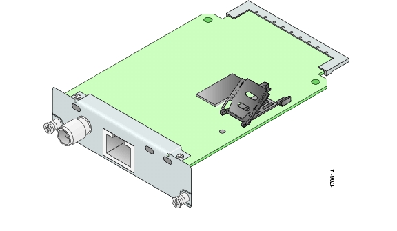
Figure 122 shows the top view of the 3G wireless WAN HWIC.

Figure 122 Top View of HWIC-3G-GSM

Figure 123 shows the bottom view of the 3G wireless WAN HWIC.

Figure 123 Bottom View of HWIC-3G-GSM

1

SIM Card Socket


HWIC-3G-CDMA

The CDMA version supports multiple bands and services:

800/1900 MHz for 1xRTT

800/1900 MHz for EVDO—Release 0 and Release A

HWIC-3G-CDMA-x is the Cisco part number for which the interface card is configured. x is a variable for carrier-specific versions.

The CDMA 3G wireless HWICs support diversity mode (dual antenna mode) in the antennas. Types of antennas include swivel-mounted dipole with extended base and ceiling-mounted antennas. The diversity mode requires two antennas located together and spaced a minimum of 7.5 inches (19 cm) for better RF reception.

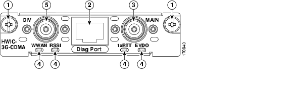
Figure 124 shows the front panel view of a CDMA 3G wireless WAN HWIC.

Figure 124 HWIC-3G-CDMA Front Panel

1

Mounting Screws

4

LEDs

2

Diagnostic Port

5

Diversity Antenna Connector

3

Main Antenna Connector


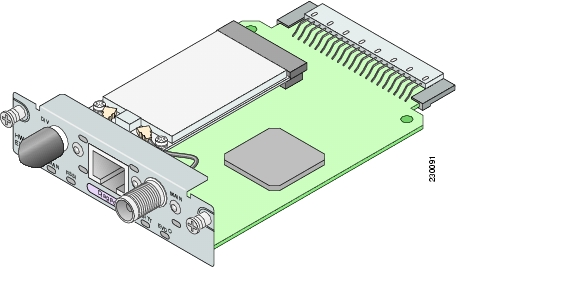
Figure 125 shows the top view of a CDMA 3G wireless WAN HWIC.

Figure 125 Top View of HWIC-3G-CDMA

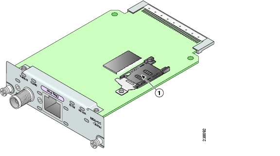
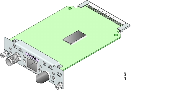
Figure 126 shows the bottom view of a CDMA 3G wireless WAN HWIC.

Figure 126 Bottom View of HWIC-3G-CDMA

Prerequisites

Before you connect, make sure you have done the following:

If you are a Cisco HWIC-3G-GSM user, before you connect the HWIC to the network, you need to install the SIM card. See the "Installing a SIM Card in the HWIC-3G-GSM" section.

Make sure you have subscribed to an appropriate GSM or CDMA service plan with your wireless service provider.

Choose an antenna that best suits your needs. See the "Connecting an Antenna with the 3G Wireless WAN HWIC" section.


Warning This equipment must be connected to an indoor antenna only. Statement 373


Although the use of two antennas is not required, both antennas can be used to take advantage of diversity antenna mode for the best RF performance.

Contact your carrier for information on network coverage, signal strength, choosing a suitable antenna, and antenna placement.


Note The diagnostics port is to be used as an advanced diagnostics tool. Do not use this port for normal operations.


Restrictions

Limitations of the 3G wireless HWICs include the following:

Only one 3G wireless HWIC is supported in the router at a time. Multiple 3G wireless HWICs on a single chassis is not a supported configuration at this time.

The 3G wireless HWIC must be installed in an HWIC slot. To determine which slots on your platform support HWICs, see the "Platform Slot Numbering and Limitations for Cisco Interface Cards" section.

Installing a SIM Card in the HWIC-3G-GSM

To install a SIM card onto the GSM HWIC, follow these steps:
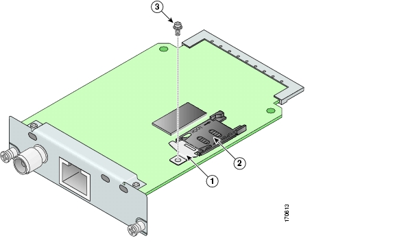

Step 1 On the bottom side of the 3G wireless HWIC, remove the bracket by unscrewing the M2.5 screw. See Figure 127 for details.

Figure 127 SIM Card installation Step 1

1

SIM Card Bracket

3

M2.5 screw

2

SIM socket


Step 2 To open the SIM cover, slide it in the direction of the "Open" arrows. Then lift the hinged cover. See Figure 128 for details.

Figure 128 SIM Cards Installation Step 2
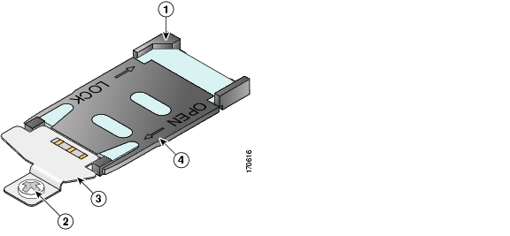
Step 3 Slide the SIM card into the slot of the open cover. See Figure 129 for details.


Note The SIM card is keyed. Make sure that the chamfer is oriented as shown in Figure 129, and the gold-plated contacts face downward to make contact with the contact pins of the SIM socket.


Figure 129

SIM Card Installation Step 3

1

Chamfer

2

SIM Card


Step 4 Close the cover by pushing it down and then sliding into the direction of the "Lock" arrows until it locks into place. Install the bracket back with the M2.5 screw as shown in Figure 130.

Figure 130 SIM Card Installation Step 4

1

Chamfer lined with keyed socket

3

Bracket

2

M2.5 Screw

4

SIM Card


3G Wireless HWIC LEDs

The 3G wireless HWIC LEDs are shown in Figure 121 and Figure 124. The functions of the LEDs are described in Table 36.

Table 36 3G wireless HWIC LED Description

LED
Description

Received Signal Strength Indication (RSSI) LED

Off: Low RSSI (under -100 dBm).

Slow Green Blink: Low or medium RSSI (-99 to -90 dBm).

Fast Green Blink: Medium RSSI (-89 to -70 dBm).

Solid Green: High RSSI (-69 dBm or higher).

Solid Yellow: No service or no RSSI detected.

WWAN LED

(Per PCI Express Mini-card Wireless WAN Standard)

Off: HWIC in reset mode or not powered.

Slow blink: Searching for service.

Solid Green: Active service; no traffic detected.

Fast Blink: Active service, and traffic detected is proportional to blink rate.

Service Type LEDs

(CDMA HWIC)

1xRTT: 1xRTT is the active service.

EVDO: 1xEVDO is the active service.

Both Off: No service is active. Both On: Both services available.


Note If the RSSI LED is solid yellow, it indicates that no service and no RSSI is detected.


Service Type LEDs

(GSM HWIC)

UMTS: UMTS is the active service.

HSDPA: HSDPA is the active service.

Both Off: Fallback service(GPRS or EDGE) is active.


Note If the RSSI LED is solid yellow, it indicates that no service and no RSSI is detected.


Connecting an Antenna with the 3G Wireless WAN HWIC

This section contains the following sub-sections:

Wireless Access Devices Safety Guidelines and Warnings

Prerequisites for Connecting Antennas

Supported Cisco Antennas and Cables

Connecting Swivel-Mount Dipole Antennas

Faceplate-Mounted and Ceiling-Mounted Antennas and Cabling

Wireless Access Devices Safety Guidelines and Warnings

The following are guidelines for wireless access devices:

Do not touch or move antenna(s) while the unit is transmitting or receiving.

Do not hold any component containing a radio so that the antenna is very close to or touching any exposed parts of the body, especially the face or eyes, while transmitting.

The use of wireless devices in hazardous locations is limited to the constraints posed by the local codes, the national codes, and the safety directors of such environments.


Warning Before working on a chassis or working near power supplies, unplug the power cord on AC units; disconnect the power at the circuit breaker on DC units. Statement 12


Warning When handling the HWICs and antennas, wear grounding wrist straps to avoid ESD damage to the card. Do not directly touch the backplane with your hand or any metal tool, or you could shock yourself. Statement 94


Warning Do not operate your wireless network device near unshielded blasting caps or in an explosive environment unless the device has been modified to be especially qualified for such use. Statement 245B


Warning In order to comply with FCC radio frequency (RF) exposure limits, antennas should be located at a minimum of 7.9 inches (20 cm) or more from the body of all persons. Statement 332


Warning This equipment must be connected to an indoor antenna only. Statement 373


Warning Do not work on the system or connect or disconnect cables during periods of lightning activity. Statement 1001


Warning Read the installation instructions before connecting the system to the power source. Statement 1004


Warning Ultimate disposal of this product should be handled according to all national laws and regulations. Statement 1040


Prerequisites for Connecting Antennas

This section contains information about connecting the antennas.


Note Before you connect the antennas, install the 3G wireless HWIC in the router. See Chapter , "Installing Cisco Interface Cards in Cisco Access Routers," for more information.


In addition to antenna orientation, installation location with respect to other wireless equipment and other RF noise sources, such as telecom and datacom equipment, plays a significant role in determining overall network performance.

Because antennas transmit and receive radio signals, their performance can be adversely affected by the surrounding environment, including distance between HWIC antenna and cellular base station, physical obstructions, or radio frequency (RF) interference.

Follow these guidelines to ensure the best possible performance:

Wherever possible, mount the 3G wireless HWIC antenna away from physical obstructions. Barriers along the line of sight between HWIC antenna and cellular base station will degrade the wireless radio signals. The 3G wireless HWICs and antennas can be installed above floor level in office environments or near the ceiling for better performance because most obstructions tend to be near floor level.

The density of the materials used in a building's construction determines the number of walls the signal must pass through and still maintain adequate coverage. Consider the following before choosing the location to install your antenna:

Paper and vinyl walls have very little effect on signal penetration.

Solid and precast concrete walls limit signal penetration to one or two walls without signal degradation.

Concrete and wood block walls limit signal penetration to three or four walls.

A signal can penetrate five or six walls constructed of drywall or wood.

A thick metal wall or a wire-mesh stucco wall causes signals to reflect back and causes poor penetration.

Avoid mounting the antenna next to a column or vertical support that could create a shadow zone and reduce the coverage area.

Keep the antenna away from reflective metal objects such as heating and air-conditioning ducts, large ceiling trusses, building superstructures, and major power cabling runs. If necessary, use an extension cable to relocate the antenna away from these obstructions.


Caution Install the 3G wireless HWIC and any antennas away from appliances that share the same frequency bands. Microwave ovens, cordless telephones, and security monitors can temporarily interfere with wireless performance.


Caution We recommend you avoid installing wireless antennas in or near rack-mounted installations that include networking equipment and computer servers whose radiated noise emissions can severely degrade radio performance.


Note If the desired installation site has a marginally acceptable level of radiated noise emissions, consider using a remotely-mounted antenna, such as a wall-mounted or ceiling-mounted antenna, for better radio performance and coverage.


Supported Cisco Antennas and Cables

Table 37 lists the Cisco antennas that are supported for use on the 3G wireless WAN HWIC

.

Table 37 Cisco Antennas Supported on the 3G Wireless HWIC 

Cisco Part Number
Antenna Type
Maximum Gain and Frequency Range
Description

3G-ANTM1919D

Dipole Omnidirectional

0 dBi
(806-960 MHz)

0 dBi
(1710-2170 MHz)

This is the default antenna. Multiband faceplate mounted dipole antenna. This antenna is included with all faceplate-mounted 3G wireless WAN HWICs. For more information, see the Cisco Multiband Swivel Mount Dipole Antenna (3G-ANTM1919D) document.

3G-ANTM1916-CM

High-Gain
Ceiling Mount Omnidirectional

1.5 dBi
(806-960 MHz)

2.5 dBi
(1710-2170 MHz)

Multiband ceiling-mounted omnidirectional antenna. For more information, see the Cisco Multiband Omnidirectional Ceiling Mount Antenna (3G-ANTM1916-CM) document.

3G-AE015-R (Antenna Extension)

Extension Base

0.8 GHz-6.0 GHz

This antenna extension is a base with a 15-foot cable included for use with dipole omnidirectional antennas. For more information, see the Cisco Extended Antenna Base (3G-AE015-R) document.


Table 38 lists insertion loss information for the ultra-low loss LMR 400 extension cables available from Cisco for use with the ceiling-mounted antenna. For more information about antenna cables, see the Antenna Cabling document.

Table 38 Cisco Extension Cables for Use with Antennas 

Cisco Product Number
Cable Length
Insertion Loss
Frequency (MHz)

3G-CAB-ULL-20

20 ft (6 m)

1.50 dB max.

2100

3G-CAB-ULL-50

50 ft (15 m)

3.50 dB max.

2100


Figure 131 shows the various antenna options with the 3G wireless WAN HWIC.

Figure 131

Antenna Options

Connecting Swivel-Mount Dipole Antennas

If you are using Cisco swivel-mounted dipole antennas, follow these steps:


Step 1 Attach an antenna to each TNC antenna connectors on the front of the 3G wireless HWIC and tighten it hand-tight.

Step 2 Orient the antennas, depending on how you intend to mount the router in which the 3G wireless HWIC is installed.

If the router is on a table or desk, orient the antennas to the left and right sides so that they are at a 90-degree angle to each other. (See Figure 131.)

If the router is on a vertical surface, such as a wall, orient the antennas up and at a 90-degree angle to each other.

If the router is on a ceiling, orient the antennas down and at a 90-degree angle to each other.


Note Although it is not absolutely necessary, for best RF performance, do not attach the dipole antenna directly to the face-plate of the 3G wireless HWIC. Use the antenna extension cable and antenna base recommended for the product.


For more information about connecting the 3G-ANTM-1919D to the HWIC-3G-GSM or HWIC-3G-CDMA, see the Cisco Multiband Swivel Mount Dipole Antenna (3G-ANTM1919D) document.

For more information about connecting the 3G-ANTM1916-CM to the HWIC-3G-GSM or HWIC-3G-CDMA, see the Cisco Multiband Omnidirectional Ceiling Mount Antenna (3G-ANTM1916-CM) document.

Faceplate-Mounted and Ceiling-Mounted Antennas and Cabling

Depending on the wireless environment, wall-mounted or ceiling-mounted antennas may be preferred for optimum radio coverage. If the length of the coaxial antenna cable is insufficient to cover the distance between the 3G wireless HWIC and the location of the installed antenna, you can use ultra-low-loss TNC extension cables between the 3G wireless HWIC and the antenna cable.

RF energy is carried between the antennas and the radio equipment through a coaxial cable. An antenna cable introduces signal loss in the antenna system for both the transmitter and the receiver. Although the cable run can be 100 feet (30 m) or more from the 3G wireless HWIC to antenna locations, the longer the cable run, the greater the signal loss. To reduce signal loss, minimize the cable length and use only ultra-low-loss antenna cables to connect radio devices to antennas.

To connect faceplate-mounted or ceiling-mounted antennas, follow the installation instructions for your antenna:

For more information about connecting the 3G-ANTM1919D to the HWIC, see the Cisco Multiband Swivel Mount Dipole Antenna (3G-ANTM1919D) document.

For more information about connecting the 3G-ANT1916-CM to the HWIC, see the Cisco Multiband Omnidirectional Ceiling Mount Antenna (3G-ANTM1916-CM) document.

For more information about connecting the 3G-AE015-R the HWIC, see the Cisco Extended Antenna Base (3G-AE015-R) document.

Related Documentation

Related documentation is available on Cisco.com or on the Product Documentation DVD. Refer to the following documents for additional information about the 3G wireless WAN interface cards.

Cisco Wireless ISR and HWIC Access Point Configuration Guide

Cisco Multiband Swivel Mount Dipole Antenna (3G-ANTM1919D)

Cisco Multiband Omnidirectional Ceiling Mount Antenna (3G-ANTM1916-CM)

Cisco Extended Antenna Base (3G-AE015-R)

Obtaining Documentation, Obtaining Support, and Security Guidelines

For information on obtaining documentation, obtaining support, providing documentation feedback, security guidelines, and also recommended aliases and general Cisco documents, see the monthly What's New in Cisco Product Documentation, which also lists all new and revised Cisco technical documentation, at:

http://www.cisco.com/en/US/docs/general/whatsnew/whatsnew.html


hometocprevnextglossaryfeedbacksearchhelp

Posted: Tue Nov 27 00:01:15 PST 2007
All contents are Copyright © 1992--2007 Cisco Systems, Inc. All rights reserved.
Important Notices and Privacy Statement.