cc/td/doc/product/access/acs_mod/cis2600/hw_inst/wic_inst
hometocprevnextglossaryfeedbacksearchhelp
PDF

Table Of Contents

Installing Cisco Interface Cards in Cisco Access Routers

Overview

Recommended Practices for Cisco Interface Cards

Safety Recommendations

Preventing Electrostatic Discharge Damage

General Maintenance Guidelines for Cisco Interface Cards

Safety Warnings for Cisco Interface Cards

Installing Cisco Interface Cards in Cisco Access Routers

Preparing to Install Cisco Interface Cards

Preparing Cisco Router Slots for Interface Card Installation

Installing Single-Wide Interface Cards

Installing Double-Wide Interface Cards

Installing Cisco Interface Cards in Cisco Network Modules

Removing or Replacing Cisco Interface Cards for Cisco Access Routers

Installing Cisco Interface Cards on the Cisco ICS 7750

Preparing to Install Interface Cards on the Cisco ICS 7750

Installing Interface Cards on the Cisco ICS 7750

Verifying Installation of Interface Cards in the Cisco ICS 7750

Installing Other Accessories in Cisco Interface Cards

Installing and Removing SFPs

Where to Go Next

Obtaining Documentation, Obtaining Support, and Security Guidelines


Installing Cisco Interface Cards in Cisco Access Routers


Revised: 6/7/07, OL-12842-01

Overview

This document provides information you should know before and during installation of Cisco interface cards in Cisco access routers, and contains the following sections:

Recommended Practices for Cisco Interface Cards

Installing Cisco Interface Cards in Cisco Access Routers

Installing Cisco Interface Cards in Cisco Network Modules

Removing or Replacing Cisco Interface Cards for Cisco Access Routers

Installing Cisco Interface Cards on the Cisco ICS 7750

Installing Other Accessories in Cisco Interface Cards

Where to Go Next

Recommended Practices for Cisco Interface Cards

This section describes recommended practices for safe and effective installation of the hardware described in this document, and includes the following sections:

Safety Recommendations

Preventing Electrostatic Discharge Damage

General Maintenance Guidelines for Cisco Interface Cards

Safety warnings included in this section apply to all Cisco interface cards used on Cisco access routers.


Note Recommendations and warnings for specific interface cards are documented in the chapter specific to the interface card.


Safety Recommendations

To prevent hazardous conditions, follow these safety recommendations while working with this equipment:

Keep tools away from walk areas where you or others could fall over them.

Do not wear loose clothing around the router. Fasten your tie or scarf and roll up your sleeves to prevent clothing from being caught in the chassis.

Wear safety glasses when working under any conditions that might be hazardous to your eyes.

Locate the emergency power-off switch in the room before you start working. If an electrical accident occurs, shut the power off.

Before working on the router, turn off the power and unplug the power cord.

Disconnect all power sources before doing the following:

Installing or removing a router chassis

Working near power supplies

Do not work alone if potentially hazardous conditions exist.

Always check that power is disconnected from a circuit.

Remove possible hazards from your work area, such as damp floors, ungrounded power extension cables, or missing safety grounds.

If an electrical accident occurs, proceed as follows:

Use caution; do not become a victim yourself.

Turn off power to the room using the emergency power-off switch.

If possible, send another person to get medical aid. Otherwise, determine the condition of the victim and then call for help.

Determine if the person needs rescue breathing or external cardiac compressions; then take appropriate action.

Preventing Electrostatic Discharge Damage

Electrostatic discharge can damage equipment and impair electrical circuitry. Electrostatic discharge occurs when electronic printed circuit cards, such as those used in Cisco interface cards, are improperly handled and can result in complete or intermittent equipment failure. Always observe the following electrostatic discharge damage (ESD) prevention procedures when installing, removing, and replacing Cisco network modules, Cisco interface cards, Cisco expansion modules, or other electronic printed circuit cards:

Make sure that the router chassis is electrically connected to earth ground.

Wear an ESD-preventive wrist strap, and make sure that it makes good contact with your skin.

Connect the wrist strap clip to an unpainted portion of the chassis frame to channel unwanted ESD voltages to ground.


Caution The wrist strap and clip must be used correctly to ensure proper ESD protection. Periodically confirm that the resistance value of the ESD-preventive wrist strap is between 1 and 10 megohms (Mohm).

If no wrist strap is available, ground yourself by touching the metal part of the router chassis.

General Maintenance Guidelines for Cisco Interface Cards

The following maintenance guidelines apply to Cisco interface cards:

Keep the router chassis area clear and dust-free during and after installation.

If you remove the chassis cover for any reason, store it in a safe place.

Do not perform any action that creates a hazard to people or makes equipment unsafe.

Keep walk areas clear to prevent falls or damage to equipment.

Follow installation and maintenance procedures as documented by Cisco Systems, Inc.

Safety Warnings for Cisco Interface Cards

The following safety warning statements apply to all hardware procedures involving Cisco interface cards for Cisco access routers. Translations of these warnings are available in the Cisco Network Modules and Interface Cards Regulatory Compliance and Safety Information document, which ships with all individual Cisco interface card orders, and is also available online.


Warning Before working on a chassis or working near power supplies, unplug the power cord on AC units; disconnect the power at the circuit breaker on DC units. Statement 12


Warning Two people are required to lift the chassis. Grasp the chassis underneath the lower edge and lift with both hands. To prevent injury, keep your back straight and lift with your legs, not your back. To prevent damage to the chassis and components, never attempt to lift the chassis with the handles on the power supplies or on the interface processors, or by the plastic panels on the front of the chassis. These handles were not designed to support the weight of the chassis. Statement 194


Warning Only trained and qualified personnel should be allowed to install or replace this equipment. Statement 1030


Warning Ultimate disposal of this product should be handled according to all national laws and regulations. Statement 1040


The following warnings apply in Australia:


Warning Do not touch the power supply when the power cord is connected. For systems with a power switch, line voltages are present within the power supply even when the power switch is OFF and the power cord is connected. For systems without a power switch, line voltages are present within the power supply when the power cord is connected. Statement 4


Warning Before working on equipment that is connected to power lines, remove jewelry (including rings, necklaces, and watches). Metal objects will heat up when connected to power and ground and can cause serious burns or weld the metal object to the terminals. Statement 43


Warning This equipment is to be installed and maintained by service personnel only as defined by AS/NZS 3260 Clause 1.2.14.3 Service Personnel. Statement 88


Warning This equipment will be inoperable when mains power fails. Statement 198


Warning Incorrect connection of this or connected equipment to a general purpose outlet could result in a hazardous situation. Statement 212


Warning Because invisible laser radiation may be emitted from the aperture of the port when no fiber cable is connected, avoid exposure to laser radiation and do not stare into open apertures. Statemen125


Warning Do not work on the system or connect or disconnect cables during periods of lightning activity. Statement 1001


Warning To avoid electric shock, do not connect safety extra-low voltage (SELV) circuits to telephone-network voltage (TNV) circuits. LAN ports contain SELV circuits, and WAN ports contain TNV circuits. Both LAN and WAN ports may use RJ-45 connectors. Use caution when connecting cables. Statement 1021


Warning Hazardous network voltages are present in WAN ports regardless of whether power to the router is OFF or ON. To avoid electric shock, use caution when working near WAN ports. When detaching cables, detach the end away from the router first. Statement 1026


Warning Ultimate disposal of this product should be handled according to all national laws and regulations. Statement 1040


Warning Before opening the chassis, disconnect the telephone-network cables to avoid contact with telephone-network voltages. Statement 1041


Warning The telecommunications lines must be disconnected 1) before unplugging the main power connector and/or 2) while the housing is open. Statement 1043


Installing Cisco Interface Cards in Cisco Access Routers

This section describes installation tasks for Cisco interface cards used on Cisco access routers, and contains the following subsections:

Preparing to Install Cisco Interface Cards

Do not install an ISDN BRI WAN interface card or an ISDN BRI network module in the same chassis as an ISDN PRI network module.

Preparing Cisco Router Slots for Interface Card Installation

Installing Blank Faceplates

Removing Blank Faceplates

Installing Interface Card Slot Dividers

Removing Interface Card Slot Dividers

Installing Single-Wide Interface Cards

Installing Double-Wide Interface Cards

Preparing to Install Cisco Interface Cards

When installing an interface card in a Cisco access router, perform the following tasks:

Table 5 Interface Card Hardware Installation Tasks for Cisco Access Routers

 
For All Cisco Access Routers Except Cisco 2800 and Cisco 3800 Series Routers
For Cisco 2800 Series and Cisco 3800 Series Routers

Step 1 

Turn off power to the router.

Turn off power to the router.

Step 2 

Remove the blank faceplate from the slot you plan to use. (See the "Removing Blank Faceplates" section.)

Remove the blank faceplate from the slot you plan to use. (See the "Removing Blank Faceplates" section.)

Step 3 

Install the interface card. (See the "Installing Single-Wide Interface Cards" section.)

Prepare the slot for the interface card form factor you are installing. (See the "Preparing Cisco Router Slots for Interface Card Installation" section.)

Step 4 

Install blank faceplates where appropriate. (See the "Removing Blank Faceplates" section.)

Install the interface card. (See the "Installing Single-Wide Interface Cards" section or the "Installing Double-Wide Interface Cards" section.)

Step 5 

Install blank faceplates where appropriate. (See the "Removing Blank Faceplates" section.)


Note Do not install an ISDN BRI WAN interface card or an ISDN BRI network module in the same chassis as an ISDN PRI network module.


Tools and Equipment Required During Cisco Interface Card Installation

You will need the following tools and equipment while working with Cisco interface cards:

Number 1 Phillips screwdriver or a small flat-blade screwdriver

ESD-preventive wrist strap

(For routers using DC power) Tape to secure DC circuit breaker handle

(For certain Cisco access routers) Voice network module for voice interface card installation

On some Cisco access routers, voice interface cards must be installed in voice network modules before being installed in the router. An additional network module or WAN interface card must be installed in the router to provide connections to an IP LAN or WAN.

Voice network modules are required for voice interface card installation in the following routers:

Cisco 2600 series

Cisco 3600 series

Cisco 3700 series


Tip For information on installing interface cards on network modules, see the "Installing Cisco Interface Cards in Cisco Network Modules" section.


Preparing Cisco Router Slots for Interface Card Installation

Several Cisco access routers have flexible interface card slots to support both single-wide and double-wide interface card form factors. Before installing an interface card, you must prepare the slot for the interface card's form factor.

The following Cisco access routers may require interface card slot preparation prior to installation of the interface card:

Cisco 2800 series routers

Cisco 3800 series routers


Tip For an introduction to Cisco interface card form factors, see the "Introduction to Cisco Interface Cards" section in Cisco Interface Cards for Cisco Access Routers.


To prepare an interface card slot for interface card installation, perform the tasks listed in Table 6 .

Table 6 Preparing Interface Card Slots for Installation

 
Double-wide to Single-wide Slot Conversion
Single-wide to Double-wide Slot Conversion

Step 1 

Remove the blank faceplates from the slots you plan to use. (See the "Removing Blank Faceplates" section.)

Remove blank faceplates from the slots you plan to use. (See the "Removing Blank Faceplates" section.)

Step 2 

Insert the slot divider. (See the "Installing Interface Card Slot Dividers" section.)

Remove the slot divider. (See the "Installing Interface Card Slot Dividers" section.)

Step 3 

Install the interface card. (See the "Installing Single-Wide Interface Cards" section.)

Install the interface card. (See the "Installing Double-Wide Interface Cards" section.)

Installing Blank Faceplates

All empty chassis slots for network modules, extension modules, or interface cards must be covered with blank faceplates to ensure proper cooling and to prevent electromagnetic interference.


Note Blank interface module faceplates are for single-wide interface card slots only.


To install a blank faceplate over an interface card slot set up for a double-wide interface card, you must prepare the slot as for single-wide interface cards. See Table 6 for information on preparing interface card slots for different interface card form factors.

To install a blank faceplate, perform the following steps:


Step 1 (For interface card slots that contained double-wide interface cards) Install a slot divider in the center of the slot to create two single-wide interface card slots.

Step 2 Align the captive screws with the threaded holes on the chassis. Using either a number 1 Phillips screwdriver or a small flat-blade screwdriver, tighten the captive screws until the blank faceplate is flush with the chassis. (See Figure 17.)

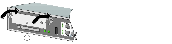
Figure 17 Installing a Blank Interface Card Faceplate

1

Blank interface card faceplate


Step 3 Repeat for every empty interface card slot.

Step 4 Continue with hardware installation tasks.


Removing Blank Faceplates

To remove blank faceplates, perform the following steps:


Step 1 Using either a number 1 Phillips screwdriver or a small flat-blade screwdriver, unscrew the captive screws and remove the blank faceplate from the chassis slot you plan to use. (See Figure 18.)

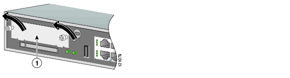
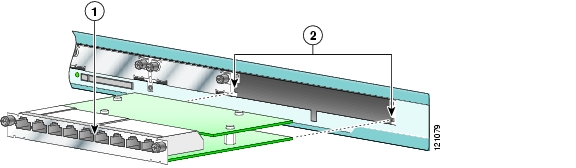
Figure 18 Removing a Blank Interface Card Faceplate

1

Blank interface card faceplate


Tip Save blank faceplates for future use.


Step 2 Continue with hardware installation tasks.


Installing Interface Card Slot Dividers

Interface card slot dividers are used to customize interface card slots for different Cisco interface card form factors. (See Figure 19 and Figure 20.) Interface card slot dividers are used on the following Cisco access routers:

Cisco 2800 series

Cisco 3800 series

To determine whether you need to install or remove slot dividers on your Cisco access router, see Table 6.

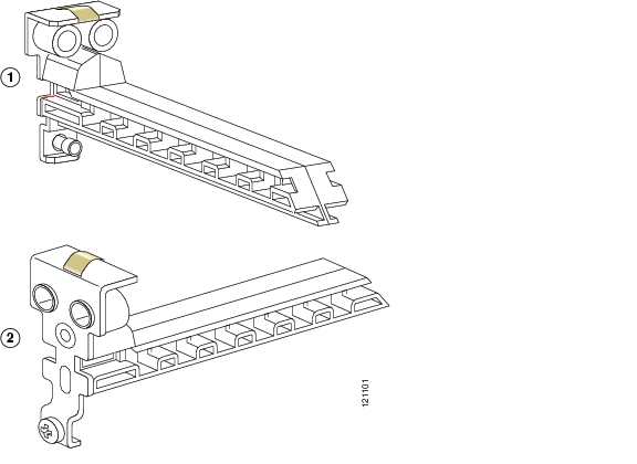
Figure 19 Slot Divider for Interface Cards Slots on Cisco 2811, Cisco 2821, Cisco 2851, and Cisco 3825 Routers

Figure 20 Slot Divider for Interface Cards Slots on Cisco 2801 and Cisco 3845 Routers

Installing Slot Dividers in Cisco 2811, Cisco 2821, Cisco 2851, and Cisco 3825 Series Routers

To install a slot divider in Cisco 2811, Cisco 2821, Cisco 2851, and Cisco 3825 series routers, perform the following steps:


Step 1 Remove any installed interface cards and blank faceplates from the router slot you plan to use.

Step 2 Guide the two halves of the slot divider between the two rails in the bottom of the interface card slot. (See Figure 21.)

Step 3 Push the slot divider in until it seats and locks into place. When the slot divider is fully seated, its outer end is flush with the front panel of the router. (See Figure 22.)

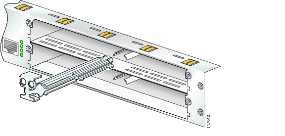
Figure 21 Inserting a Slot Divider into an Interface Card Slot

Step 4 Gently pull the slot divider to check for complete seating. If properly seated, it does not come out. (See Figure 22.)

Figure 22 Slot Divider Installed in an Interface Card Slot


Installing Slot Dividers in Cisco 2801 and Cisco 3845 Routers

To install a slot divider in Cisco 2801 and Cisco 3845 routers, perform the following steps:


Step 1 Guide the slot divider between the two rails in the bottom of the interface card slot. (See Figure 23.) Push the slot divider in until it is fully seated. When the slot divider is fully seated, its outer end is flush with the front panel of the router.

Figure 23 Inserting a Slot Divider into an Interface Card Slot on a Cisco 2801 or Cisco 3845 Router

1

Slot divider

2

Slot divider rails


Step 2 Tighten the retention screw on the slot divider.


Removing Interface Card Slot Dividers

Slot dividers are removed to permit use of double-wide interface cards in modular router slots. To determine whether you need to install or remove slot dividers on your Cisco access router, see Table 6.

To remove slot dividers from network module slots from Cisco 2811, Cisco 2821, Cisco 2851, and Cisco 3825 series routers, perform the following steps:


Step 1 Remove any installed interface cards and blank faceplates from the router slot you plan to use.

Step 2 Reach into the interface card slots on both sides of the slot divider, and squeeze the two halves of the slot divider together. (See Figure 24.)

Figure 24 Removing a Slot Divider from a Cisco 2811, Cisco 2821, Cisco 2851, or Cisco 3825 Series Router

Step 3 Pull the slot divider straight out of the interface card slot.


To remove slot dividers from network module slots from Cisco 2801 and Cisco 3845 routers, perform the following steps:


Step 1 Remove any installed interface cards and blank faceplates from the router slot you plan to use.

Step 2 Loosen the retention screw on the slot divider.

Step 3 Pull the slot divider straight out of the interface card slot.


Installing Single-Wide Interface Cards


Caution WAN interface cards and voice interface cards are not interchangeable. Voice interface cards cannot be installed in a WAN interface card slot or a 2-slot WAN network module, and WAN interface cards cannot be installed in voice network modules. To prevent damage to the card, confirm that the slot or network module you intend to use supports the kind of interface card you intend to install.

Interface cards can be installed either before or after mounting the router, whichever is most convenient. To install a single-wide interface card, follow these steps:


Step 1 Turn off electrical power to the router. Leave the power cable plugged in to channel ESD voltages to ground.

(For the Cisco MWR 1941-DC router) Turn off power by turning the DC power source circuit breaker to OFF. Tape the circuit breaker in the OFF position. To channel ESD voltages to ground, do not remove the wire from the ground lug.


Warning Before performing any of the following procedures, ensure that power is removed from the DC circuit. To ensure that all power is OFF, locate the circuit breaker on the panel board that services the DC circuit, switch the circuit breaker to the OFF position, and tape the switch handle of the circuit breaker in the OFF position. Statement 7


Step 2 Remove all network cables, including telephone cables, from the router.


Caution To prevent damage to the interface card, turn off electrical power and disconnect network cables from the chassis before inserting an interface card into an installed network module or router slot.

Step 3 Remove blank faceplates installed over the slot you intend to use. (See the "Removing Blank Faceplates" section.)


Tip Save blank faceplates for future use.


Step 4 (For certain Cisco routers) Prepare the slot for the interface card form factor you are installing. (See the "Preparing Cisco Router Slots for Interface Card Installation" section.)

Step 5 Align the interface card with the guides in the chassis walls or slot divider and slide it gently into the slot (see Figure 25).


Caution Do not touch the interface card board. Handle the interface card by the edges of the faceplate to reduce the risk of damage to the card.


Tip (For Cisco 2600 series routers only) Install WAN interface cards in slot W0 first to avoid affecting your router configuration.


Figure 25 Installing Single-Wide Interface Cards in Cisco Access Routers

1

Interface card

2

Card guides


Step 6 Using the faceplate, push the interface card into place until you feel the edge connector seat securely into the connector on the router backplane. The interface card faceplate should contact the chassis rear panel.


Caution Do not connect cables to an interface card until you have installed it.

Step 7 Using a number 1 Phillips or flat-blade screwdriver, tighten the captive mounting screws on the interface card faceplate.

Step 8 Proceed with connecting the interface card to the network and powering up the router.


Tip See the "Where to Go Next" section for information on locating additional hardware documentation.


Warning After wiring the DC power supply, remove the tape from the circuit breaker switch handle and reinstate power by moving the handle of the circuit breaker to the ON position. Statement 8


Installing Double-Wide Interface Cards

Interface cards can be installed either before or after mounting the router, whichever is most convenient. To install a double-wide interface card, follow these steps:


Step 1 Turn off electrical power to the router. Leave the power cable plugged in to channel ESD voltages to ground.

Step 2 Remove all network cables, including telephone cables, from the router.


Caution To prevent damage to the interface card, turn off electrical power and disconnect network cables from the chassis before inserting an interface card into an installed network module or router slot.

Step 3 Remove the blank faceplates installed over the slot you intend to use. (See the "Removing Blank Faceplates" section.)


Tip Save blank faceplates for future use.


Step 4 Remove the slot divider. (See the "Removing Interface Card Slot Dividers" section.)

Step 5 Align the interface card with the guides in the chassis walls or slot divider, and slide it gently into the slot. (See Figure 26.)

Figure 26 Installing Double-Wide Interface Cards in Cisco Access Routers

1

Interface card

2

Card guides


Caution Do not touch the interface card board. Handle the interface card by the edges of the faceplate to reduce the risk of damage to the card.

Step 6 Using the faceplate, push the interface card into place until you feel the edge connector seat securely into the connector on the router backplane. The interface card faceplate should contact the chassis rear panel.


Caution Do not connect cables to an interface card until you have installed it.

Step 7 Using a number 1 Phillips or flat-blade screwdriver, tighten the captive mounting screws on the interface card faceplate.

Step 8 Proceed with connecting the interface card to the network and powering up the router.


Tip See the "Where to Go Next" section for information on locating additional hardware documentation.


Installing Cisco Interface Cards in Cisco Network Modules


Caution WAN interface cards and voice interface cards are not interchangeable. Voice interface cards cannot be installed in a WAN interface card slot or a two-slot WAN network module, and WAN interface cards cannot be installed in voice network modules. To prevent damage to the card, confirm that the slot or network module you intend to use supports the kind of interface card you intend to install.

Some Cisco network modules have one or two interface card slots, which support a variety of voice and data interface cards. To determine which interface cards are supported in your network module, see the Cisco Network Modules Hardware Installation Guide.

The following conditions apply to ISDN BRI and ISDN PRI network modules and interface cards:

Do not install an ISDN BRI WAN interface card or an ISDN BRI network module in the same chassis as an ISDN PRI network module unless you are using Cisco IOS Release 11.3(3)T or a later release.

Do not install newer BRI WAN interface cards in the same network module as older BRI WAN interface cards. To identify newer BRI WAN interface cards, examine the B-channel LEDs. Newer BRI WAN interface cards have B-channel LEDs that are arranged horizontally. Older BRI WAN interface cards have B-channel LEDs that are arranged vertically.

To install an interface card in a 1- or 2-slot network module, perform the following steps:


Step 1 Turn off electrical power to the router. Leave the power cable plugged in to channel ESD voltages to ground.

(For the Cisco MWR 1941-DC router) Turn off power by turning the DC power source circuit breaker to OFF. Tape the circuit breaker in the OFF position. To channel ESD voltages to ground, do not remove the wire from the ground lug.

The following warning applies to routers that use a DC power supply:


Warning Before performing any of the following procedures, ensure that power is removed from the DC circuit. To ensure that all power is OFF, locate the circuit breaker on the panel board that services the DC circuit, switch the circuit breaker to the OFF position, and tape the switch handle of the circuit breaker in the OFF position. Statement 7


Warning To avoid electric shock, do not insert a WAN or voice interface card into a 2-slot module while power is on or network cables are connected. Statement 68


Step 2 Remove all network cables, including telephone cables, from the router.


Caution To prevent damage to the interface card, turn off electrical power and disconnect network cables from the chassis before inserting an interface card into an installed network module or router slot.

Step 3 Using a number 1 Phillips or flat-blade screwdriver, loosen the screws on the blank interface card faceplate. (See Figure 27.) Remove the blank faceplate.

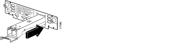
Figure 27 Blank Interface Card Faceplate


Tip Save blank interface card faceplates for future use.


Step 4 Align the interface card with the guides in the slot on the network module and slide it gently into place until the edge connector is seated into the connector on the module. (See Figure 28.)

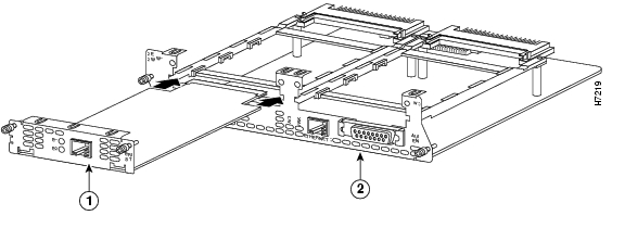
Figure 28 Installing an Interface Card in a Network Module (Typical)

1

Interface card

2

2-slot network module


Step 5 Using a number 1 Phillips or flat-blade screwdriver, tighten the captive mounting screws into the holes on the network module faceplate.

Step 6 Reinstall the network interface cables and power up the router.

The following warning applies to routers that use a DC power supply:


Warning After wiring the DC power supply, remove the tape from the circuit breaker switch handle and reinstate power by moving the handle of the circuit breaker to the ON position. Statement 8


Removing or Replacing Cisco Interface Cards for Cisco Access Routers


Caution WAN interface cards and voice interface cards are not interchangeable. To prevent damage to the card, confirm that you are installing the correct type of interface card for the slot or network module you intend to use.

To remove or replace an interface card from a Cisco access router, perform these steps:


Step 1 Turn off electrical power to the router. Leave the power cable plugged in to channel ESD voltages to ground.

(For the Cisco MWR 1941-DC router) Turn off power by turning the DC power source circuit breaker to OFF. Tape the circuit breaker in the OFF position. To channel ESD voltages to ground, do not remove the wire from the ground lug.


Warning Before performing any of the following procedures, ensure that power is removed from the DC circuit. To ensure that all power is OFF, locate the circuit breaker on the panel board that services the DC circuit, switch the circuit breaker to the OFF position, and tape the switch handle of the circuit breaker in the OFF position. Statement 7


Step 2 Remove all network cables, including telephone cables, from the router.


Caution To prevent damage to the interface card, turn off electrical power and disconnect network cables from the chassis before inserting an interface card into an installed network module or router slot.


Timesaver To make reconnection of network interface cables easier, label the cables or prepare a network cabling diagram before removing network interface cables from the network module.


Step 3 Using a number 1 Phillips or flat-blade screwdriver, loosen the captive mounting screws on the interface card faceplate.

Step 4 Using the faceplate edges, pull the interface card from the router slot.


Tip Use the thumbscrews to pull the interface card faceplate away from the router chassis until you can grip the faceplate with your fingers.


Caution Do not touch the interface card board. Handle the interface card by the edges of the faceplate to reduce the risk of damage to the card.

Step 5 Take one of the following actions:

If you are replacing the interface card, use the procedures described in the "Installing Cisco Interface Cards in Cisco Access Routers" section.


Caution Do not connect cables to an interface card until you have installed it.

If you are not replacing the interface card, install a blank faceplates over the empty slots to ensure proper airflow. (See the "Installing Blank Faceplates" section.)


Tip See the "Where to Go Next" section for information on locating additional hardware documentation.


Warning After wiring the DC power supply, remove the tape from the circuit breaker switch handle and reinstate power by moving the handle of the circuit breaker to the ON position. Statement 8


Installing Cisco Interface Cards on the Cisco ICS 7750

This section describes how to install Cisco interface cards on the Cisco Integrated Communication System (ICS) 7750, and contains the following subsections:

Preparing to Install Interface Cards on the Cisco ICS 7750

Installing Interface Cards on the Cisco ICS 7750

Cisco interface cards are installed in the Cisco ICS 7750 through either the multiservice route processor (MRP) or analog station interface 81 (ASI 81) cards. For more information about these cards, see the "Processor Cards Feature Summary" chapter in the Cisco ICS 7750 System Description document.

The MRP has two interface card slots (slot 0, slot 1) and the ASI 81 has one interface card slot (slot 1).

Preparing to Install Interface Cards on the Cisco ICS 7750

Before installing an interface card into the MRP or ASI 81, perform the following tasks:

Verify that the MRP or ASI 81 card has the minimum Cisco IOS release required to support your interface card.

Determine whether additional voice traffic due to installed voice or voice/WAN interface cards will require additional digital signal processors (DSPs). If additional DSPs are required, install up to two additional packet voice data modules (PVDMs) on each MRP or ASI 81 card to provide more processing power.


Timesaver To configure digital voice ports correctly, any additional PVDMs must be installed before the interface card is installed on the MRP or ASI 81 card, or the Cisco ICS 7750 will not be recognized as a voice port.


Tip To see a list of voice ports on the Cisco ICS 7750, use the Cisco IOS show running-config or show diag commands.


Installing Interface Cards on the Cisco ICS 7750

To install an interface card on an MRP or ASI 81 card for installation into the Cisco ICS 7750, perform the following steps:


Step 1 If the MRP or ASI 81 is already installed in the chassis, back up the card configuration using the ICS System Manager application. For more information on backing up card configurations, refer to the ICS System Manager online help system.

If the MRP or ASI 81 is not installed in the chassis, go to Step 7.


Caution Do not power down the chassis using the power supply switch or by unplugging the power supply. Doing so may cause the Cisco ICS 7750 to lose important configuration data and interrupts any applications or functions running on other cards in the chassis.


Timesaver You do not have to turn off power to the Cisco ICS 7750 for this procedure. If the Cisco ICS 7750 is running, do not power down the entire chassis by using the chassis power supply switch or by unplugging the power supply.


Step 2 Shut down operations on the MRP or ASI 81 card by pressing the SHTDN button on the card faceplate. The status LED on the card blinks; after several minutes, the status LED goes off. Wait for the status LED to go off before continuing to Step 3.

Step 3 Put on an ESD-preventive wrist strap and attach the wrist strap to an unpainted chassis surface to establish a ground.


Caution To prevent ESD damage, handle the cards only by the edges, and use an ESD-preventive wrist strap or other grounding device.

Step 4 Disconnect any cables attached to the front of the interface card and secure them out of the way, using cable ties if necessary.

Step 5 Loosen the lock-down screws at the top and bottom of the MRP or ASI 81 card.

Step 6 Press the upper and lower extractor levers away from the chassis at the same time, disengaging the MRP or ASI 81 card from the Cisco ICS 7750 backplane. Pull the card away from the backplane about 1 inch (2.5 cm) to disengage it from the backplane. Do not completely remove the card from the chassis.


Caution Always use the extractor levers to disengage or seat cards. Failure to use the levers can cause erroneous system error messages indicating a card failure.


Caution Do not use the extractor levers to lift or support the weight of the cards.


Caution Devices on system cards can get hot during operation. To remove a card, hold the card by the faceplate and bottom edge. Allow the card to cool before touching any other part of it or placing it an antistatic bag.

Step 7 If you are replacing an interface card, or if there is a blank interface card faceplate already installed in the MRP or ASI 81 card, use either a number 2 Phillips screwdriver or a small flat-blade screwdriver to remove the interface card or blank faceplate.


Tip Save the blank faceplate for future use.


Note If you remove an interface card while the MRP or ASI 81 is running, the interface card configuration is lost until the system card reboots.


Step 8 Align the new interface card with the guides in the ASI 81 or MRP slot, and slide it gently into the slot. (See Figure 29.)

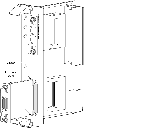
Figure 29 Installing Interface Cards into an MRP Card

Step 9 Push the interface card into place until you feel its edge connector seat securely into the connector on the MRP or ASI 81.

Step 10 Using a Phillips or flat-blade screwdriver, tighten the interface card mounting screws until the interface card faceplate makes contact with the faceplate on the MRP or ASI 81 card.


Tip If an interface card slot on the ASI 81 or MRP is unoccupied, install a filler panel to enable proper airflow.


Step 11 Align the ASI 81 or MRP with the upper and lower card guides in the chassis slot, and make sure that the extractor levers are in the open position (pointing outward).

Step 12 With the top and bottom edges of the ASI 81 or MRP in the card guides, gently slide the card into the chassis until you feel resistance. Because there are grounding clips near the front and rear of the card guides, you might need to increase the amount of force that you use to get the card past the grounding clips. If you encounter extreme resistance, pull the card out slightly, and push it back in again.

Step 13 Press the upper and lower extractor levers inward at the same time until they lock into their slots. This step firmly seats the ASI 81 or MRP into the chassis.

Step 14 Connect cables to the ASI 81 or MRP interfaces.

Step 15 The status LED on the ASI 81 or MRP blinks green as it boots. Wait until the LED is steady green, and then verify that the interface card installation. See the "Verifying Installation of Interface Cards in the Cisco ICS 7750" section.


Verifying Installation of Interface Cards in the Cisco ICS 7750

To verify that an interface card was installed successfully, check the system card LEDs using Table 7.

Table 7 LEDs Used to Verify Interface Card Installation on the Cisco ICS 7750

LED
Description

Status

Shows the status of the MRP or ASI 81:

Blinks green while the card is booting up.

Green after the power-on self-test (POST) is complete, and the card is operating correctly.

Slot 0

Shows the slot status of an MRP card that has an interface card installed in the slot, or of an 8-port FXS card in the ASI 81:

Green shows that the WIC, VWIC, or VIC is correctly installed in the slot.

Off indicates that no card is installed in the slot, or that a card is incorrectly installed in the slot.

Slot 1


Installing Other Accessories in Cisco Interface Cards

Certain Cisco interface cards support a variety of additional modules, such as small form-factor pluggable modules (SFPs).

Installing and Removing SFPs

SFPs are hot-swappable Ethernet interfaces that can be installed directly into Cisco interface cards. The following Cisco interface cards currently support SFPs:

HWIC-1GE-SFP

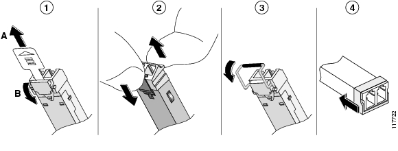
This section describes a generic installation and removal procedure. SFPs use various latch designs (see Figure 31) to secure the module in the SFP port.


Note Latch designs are not linked to SFP model or technology type; for information on the SFP technology type and model, see the label on the side of the SFP.


To install an SFP in a Cisco interface card, perform the following steps:


Step 1 Install the interface card in the router. (See the "Installing Cisco Interface Cards in Cisco Access Routers" section.)


Warning Because invisible laser radiation may be emitted from the aperture of the port when no fiber cable is connected, avoid exposure to laser radiation and do not stare into open apertures. Statement 125


Step 2 Slide the SFP into the housing on the interface card until it is locked into position. (See Figure 30.) The SFP is designed to prevent improper insertion.


Tip If the SFP uses a bale-clasp latch (see Figure 31), the bale-clasp handle should be on top of the SFP in the closed position for proper seating of the SFP module.


Figure 30 Installing an SFP in Cisco Interface Cards


Caution Do not remove the optical port plugs used on the SFP (gray color in the illustration) until you are ready to connect cabling to the interface card.

Step 3 (For optical SFPs) Remove the plugs from the SC connectors on the SFP.

Step 4 Connect the interface card to the network.


Timesaver If installing the SFP in an uninstalled interface card, install the interface card (see "Installing Cisco Interface Cards in Cisco Access Routers") before connecting the interface card to the network.


To remove a SFP from an interface card, perform the following steps:


Step 1 Disconnect all cables from the SFP.


Warning Because invisible laser radiation may be emitted from the aperture of the port when no fiber cable is connected, avoid exposure to laser radiation and do not stare into open apertures. Statement 125


Caution The latching mechanism used on many SFPs locks the SFP into place whenever cables are connected. Do not pull on the cabling in an attempt to remove the SFP.

Step 2 Disconnect the SFP latch. (See Figure 31.)

Figure 31 Disconnecting SFP Latch Mechanisms

1

Sliding latch

2

Swing and slide latch

3

Bale-clasp latch

4

Plastic collar latch


Tip Use a pen, screwdriver, or other small straight tool to gently release the bale-clasp handle if you cannot reach it with your fingers.


Step 3 Grasp the SFP on both sides and remove it from the interface card.


Where to Go Next

For an introduction to Cisco interface cards, go to Cisco Interface Cards for Cisco Access Routers.

For regulatory compliance and safety information, see the Cisco Network Modules and Interface Cards Regulatory Compliance and Safety Information document.

To locate hardware information about specific interface cards, go to the "Platform Support for Cisco Interface Cards" section in Cisco Interface Cards for Cisco Access Routers.

Obtaining Documentation, Obtaining Support, and Security Guidelines

For information on obtaining documentation, obtaining support, providing documentation feedback, security guidelines, and also recommended aliases and general Cisco documents, see the monthly What's New in Cisco Product Documentation, which also lists all new and revised Cisco technical documentation, at:

http://www.cisco.com/en/US/docs/general/whatsnew/whatsnew.html

© 2007 Cisco Systems, Inc. All rights reserved.


hometocprevnextglossaryfeedbacksearchhelp

Posted: Mon Nov 26 23:53:55 PST 2007
All contents are Copyright © 1992--2007 Cisco Systems, Inc. All rights reserved.
Important Notices and Privacy Statement.