cc/td/doc/product/access/acs_mod/cis2600/hw_inst/wic_inst
hometocprevnextglossaryfeedbacksearchhelp
PDF

Table Of Contents

Access Point High-Speed WAN Interface Cards

Overview

Access Point High-Speed WAN Interface Cards

Access Point HWIC Limitations

Access Point HWIC Safety Guidelines and Warnings

Access Point HWIC LEDs

Supported Cisco Radio Antennas

Connecting Radio Antennas to the Access Point HWIC

Related Documentation

Obtaining Documentation, Obtaining Support, and Security Guidelines


Access Point High-Speed WAN Interface Cards


Revised: 6/7/07, OL-12854-01

Overview

This document describes access point high-speed WAN interface cards (HWICs) and how to connect access point HWICs to a network, and contains the following sections:

Access Point High-Speed WAN Interface Cards

Related Documentation

Obtaining Documentation, Obtaining Support, and Security Guidelines

For an overview of Cisco interface cards used for Cisco access routers see the Cisco Interface Cards for Cisco Access Routers document.

Access Point High-Speed WAN Interface Cards

This section describes access point HWICs and contains the following sections:

Access Point HWIC Limitations

Access Point HWIC Safety Guidelines and Warnings

Access Point HWIC LEDs

Supported Cisco Radio Antennas

Connecting Radio Antennas to the Access Point HWIC

The access point HWIC houses one radio (single-mode) or two radios (dual-mode) for connection to a wireless LAN. There are two access point HWICs:

Single-mode access point HWIC with 2.4-GHz radio for 802.11b/g operations. (See Figure 132.) The following are the Cisco part numbers and the geographic regions for which the interface cards are configured:

HWIC-AP-G-A—North America

HWIC-AP-G-E—Europe

HWIC-AP-G-J—Japan


Note The wireless operations can be configured by using the Cisco Router and Security Device Manager (SDM) web-based application, or by using the Cisco IOS command-line interface (CLI). See the Cisco Router and Security Device Manager (SDM) Quick Start Guide or the Cisco Access Router Wireless Configuration Guide for more information.


Dual-mode access point HWIC with two radios: one 2.4-GHz 802.11b/g radio and one 5-GHz 802.11a radio. (See Figure 133.) The following are the Cisco part numbers and the geographic regions for which the interface cards are configured:

HWIC-AP-AG-A—North America

HWIC-AP-AG-E—Europe


Note Access point HWICs with the 5-GHz 802.11a radio that are used in Europe may be required to use Dynamic Frequency Selection (DFS) to detect and avoid interfering with radar signals to comply with that regulatory domain. DFS operates only on routers running Cisco IOS version 12.4(2)XA or higher.


HWIC-AP-AG-J—Japan

Both the single-mode and dual-mode access point HWICs support diversity in the radio antennas. Types of antennas include swivel-mount dipole, wall-mount, and ceiling-mount antennas.


Note For regulatory information about the access point HWIC and supported antennas, see the Declarations of Conformity and Regulatory Information for Cisco Access Products with 802.11a/b/g and 802.11b/g Radios document.


Figure 132 shows a single-mode access point HWIC, and Figure 133 shows a dual-mode access point HWIC.


Note Although the single-mode access point HWIC has two sets of LEDs, the LEDs on the left side of the single-mode access point HWIC are nonfunctioning and do not light.


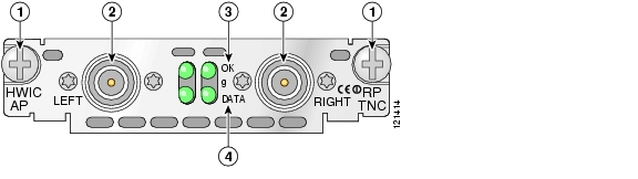
Figure 132 Single-Mode Access Point HWIC Front Panel

1

Mounting screws

3

OK LED for the 802.11b/g radio

2

RP-TNC connectors

4

DATA LED for the radio


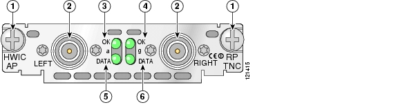
Figure 133 Dual-Mode Access Point HWIC Front Panel

1

Mounting screws

4

OK LED for the 802.11b/g radio

2

RP-TNC connectors

5

DATA LED for the 802.11a radio

3

OK LED for the 802.11a radio

6

DATA LED for the 802.11b/g radio


Access Point HWIC Limitations

Limitations of the single-mode and dual-mode access point HWICs include the following:

Only one access point HWIC is supported in the router at a time. Installation of two access point HWICs in the router is not supported.

The access point HWIC must be installed in an HWIC slot. To determine which slots on your platform support HWICs, see the "Platform Slot Numbering and Limitations for Cisco Interface Cards" section.

The 4.9-GHz band is not supported.

Although the use of two antennas is not required, both antennas should be used to take advantage of diversity for the best RF performance.

Access Point HWIC Safety Guidelines and Warnings

The following are guidelines for wireless access devices:

Do not touch or move antenna(s) while the unit is transmitting or receiving.

Do not hold any component containing a radio so that the antenna is very close to or touching any exposed parts of the body, especially the face or eyes, while transmitting.

The use of wireless devices in hazardous locations is limited to the constraints posed by the local codes, the national codes, and the safety directors of such environments.


Note For regulatory information about the access point HWIC, see the Declarations of Conformity and Regulatory Information for Cisco Access Products with 802.11a/b/g and 802.11b/g Radios document.


Warning Before working on a chassis or working near power supplies, unplug the power cord on AC units; disconnect the power at the circuit breaker on DC units. Statement 12


Warning During this procedure, wear grounding wrist straps to avoid ESD damage to the card. Do not directly touch the backplane with your hand or any metal tool, or you could shock yourself. Statement 94


Warning Do not operate your wireless network device near unshielded blasting caps or in an explosive environment unless the device has been modified to be especially qualified for such use. Statement 245B


Warning In order to comply with FCC radio frequency (RF) exposure limits, antennas should be located at a minimum of 7.9 inches (20 cm) or more from the body of all persons. Statement 332


Warning Do not work on the system or connect or disconnect cables during periods of lightning activity. Statement 1001


Warning Read the installation instructions before connecting the system to the power source. Statement 1004


Warning Ultimate disposal of this product should be handled according to all national laws and regulations. Statement 1040


Access Point HWIC LEDs

The access point HWIC LEDs are shown in Figure 132 and Figure 133. The functions of the LEDs are described in Table 39.

Table 39 Access Point HWIC LEDs

LED
Description

OK

Off if the access point HWIC is administratively shut down or there is no service set identifier (SSID) configured.

Blinks if an SSID is configured but there is no client associated.

On (solid green) if one or more clients are associated.

DATA

Off if the access point HWIC is administratively shut down or there is no SSID configured.

Blinks if there is activity (sending or receiving packets).


Supported Cisco Radio Antennas

Table 40 lists the Cisco antennas that are supported for use on the single-mode access point HWIC.

Table 40 Cisco Antennas Supported on the Single-Mode Access Point HWIC 

Cisco Part Number
Antenna Type
Maximum Gain
Description

AIR-ANT4941

Omnidirectional

2.2 dBi

This is the default antenna. Swivel-mount dipole antenna operating in the 2.4-to 2.5-GHz band. This antenna is designed for use with Cisco wireless products utilizing an RP-TNC connector. For more information, see the Cisco Aironet 2.4 GHz Articulated Dipole Antenna (AIR-ANT4941) document.

AIR-ANT1728

Omnidirectional

5.2 dBi

Ceiling-mount antenna operating in the 2.4- to 2.5-GHz band. This antenna has a clip that allows it to be mounted to a drop-ceiling cross member. For more information, see the Cisco Aironet High-Gain Omnidirectional Ceiling Mount Antenna (AIR-ANT1728) document.

Note This antenna is not supported in Japan.

AIR-ANT3549

Patch

9 dBi

Wall-mount antenna operating in the 2.4- to 2.5-GHz band.

Note This antenna is not supported in the United States and Canada.

AIR-ANT5959

Diversity omnidirectional

2 dBi

Ceiling-mount antenna operating in the 2.4- to 2.5-GHz band. This antenna has a clip that allows it to be mounted to a drop-ceiling cross member. For more information, see the Cisco Aironet 2-dBi Diversity Omnidirectional Ceiling Mount Antenna (AIR-ANT5959) document.


Table 41 lists the Cisco antennas that are supported for use on the dual-mode access point HWIC.

Table 41 Cisco Antennas Supported on the Dual-Mode Access Point HWIC 

Cisco Part Number
Antenna Type
Maximum Gain
Description

AIR-ANTM2050D-R

Omnidirectional

2.2 dBi in the 2.4-GHz band

5 dBi in the 5-GHz band

This is the default antenna. Swivel-mount dipole antenna operating in the 2.4- to 2.5-GHz band. This antenna is designed for use with Cisco wireless products utilizing an RP-TNC connector. For more information, see the Cisco Multiband Swivel-Mount Dipole Antenna (AIR-ANTM2050D-R) document.

AIR-ANTM4050V-R

Diversity omnidirectional

4 dBi in the 2.4-GHz band

5 dBi in the 5-GHz band

Ceiling-mount antenna operating in the 2.4- to 2.5-GHz band. This antenna has a clip that allows it to be mounted to a drop-ceiling cross member. For more information, see the Cisco Multiband Diversity Omnidirectional Ceiling-Mount Antenna (AIR-ANTM4050V-R) document.

AIR-ANTM5560P-R

Patch

5.5 dBi in the 2.4-GHz band

6 dBi in the 5-GHz band

Wall-mount antenna operating in the 2.4- to 2.5-GHz band. For more information, see the Cisco Multiband Wall-Mount Antenna (AIR-ANTM5560P-R) document.


Connecting Radio Antennas to the Access Point HWIC

This section contains information about connecting the radio antennas.


Note Before connecting the radio antennas, install the access point HWIC in the router. See Installing Cisco Interface Cards in Cisco Access Routers for more information.


In addition to antenna orientation, wireless access point installation location with respect to all wireless clients plays a significant role in determining overall network performance. Clients at the furthest coverage points might have 10% to 50% of the bandwidth of clients close to it. Wireless network coverage in one area or location might need to be lowered to improve the performance of other clients.

Because antennas transmit and receive radio signals, their performance can be adversely affected by the surrounding environment including distance between access point and client, physical obstructions, or radio frequency (RF) interference.

Follow these guidelines to ensure the best possible performance:

Wherever possible, mount the access point HWIC and antenna where the wireless devices would be within sight and avoid physical obstructions. Barriers along the line of sight between client and access point will degrade the wireless radio signals. access point HWICs and antennas can be installed above floor level in office environments or near the ceiling for better performance since most obstructions tend to be near floor level.

The density of the materials used in a building's construction determines the number of walls the signal must pass through and still maintain adequate coverage. Consider the following before choosing the location to install your antenna:

Paper and vinyl walls have very little effect on signal penetration.

Solid and precast concrete walls limit signal penetration to one or two walls without degrading coverage.

Concrete and wood block walls limit signal penetration to three or four walls.

A signal can penetrate five or six walls constructed of drywall or wood.

A thick metal wall or wire-mesh stucco walls causes signals to reflect back and cause poor penetration.

Avoid mounting the antenna next to a column or vertical support that could create a shadow zone and reduce the coverage area.

Keep the antenna away from reflective metal objects such as heating and air-conditioning ducts, large ceiling trusses, building superstructures, and major power cabling runs. If necessary, use an extension cable to relocate the antenna away from these obstructions.


Caution Install the access point HWIC and any antennas away from appliances that share the same frequency bands. Microwave ovens, cordless telephones, and security monitors can temporarily interfere with wireless performance.


Caution We recommend you avoid installing wireless antennas in or near rack-mounted installations that include networking equipment and computer servers whose radiated noise emissions can severely degrade radio performance.


Note If the desired installation site has a marginally acceptable level of radiated noise emissions, consider using a remote-mounted antenna, such as a wall-mount or ceiling-mount antenna, for better radio performance and coverage.


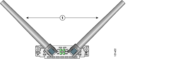
Swivel-Mount Dipole Antennas

If you are using Cisco swivel-mount dipole antennas, follow these steps:


Step 1 Attach an antenna to each of the RP-TNC antenna connectors on the front of the access point HWIC and tighten it hand-tight.

Step 2 Orient the antennas depending on how you intend to mount the router in which the access point HWIC is installed.

If the router is on a table or desk, orient the antennas to the left and right sides so that they are at a 90-degree angle to each other. (See Figure 134.)

If the router is on a vertical surface, such as a wall, orient the antennas up and at a 90-degree angle to each other.

If the router is on a ceiling, orient the antennas down and at a 90-degree angle to each other.


Note Although it is not absolutely necessary, for best RF performance, orient the antennas as shown in Figure 134.


Figure 134 Swivel-Mount Dipole Antenna Positions for Use with Desktop Router

1

Swivel-mount dipole antennas


For more information about connecting the AIR-ANT4941 to the HWIC-AP-G, see the Cisco Aironet 2.4-Ghz Articulated Dipole Antenna (AIR-ANT4941) document.

For more information about connecting the AIR-ANTM2050D-R to the HWIC-AP-AG, see the Cisco Multiband Swivel-Mount Dipole Antenna (AIR-ANTM2050D-R) document.

Wall-Mount and Ceiling-Mount Antennas and Cabling

Depending on the wireless environment, wall-mounted or ceiling-mounted antennas may be preferred for optimum radio coverage. If the length of the coaxial antenna cable is insufficient to cover the distance between the access point HWIC and the location of the installed antenna, you can use low-loss RP-TNC extension cables between the access point HWIC and the antenna cable.

RF energy is carried between the antennas and the radio equipment through a coaxial cable. An antenna cable introduces signal loss in the antenna system for both the transmitter and the receiver. Although the cable run can be 100 feet (30 m) or more from the access point HWIC to antenna locations, the longer the cable run, the greater the signal loss. To reduce signal loss, minimize the cable length and use only low-loss or ultra low-loss antenna cables to connect radio devices to antennas.

Table 42 lists transmission loss information about low-loss and ultra-low-loss extension coaxial cables available from Cisco. For more information about antenna cables, see the Antenna Cabling document.

Table 42 Cisco Extension Coaxial Cables 

Cisco Product Number
Cable Length
Transmission Loss

AIR-CAB020LL-R

20 ft (6 m)

2.4-GHz: 1.3 dBi

5-GHz: 2.5 dBi

AIR-CAB050LL-R

50 ft (15 m)

2.4-GHz: 3.3 dBi

5-GHz: 5.75 dBi

AIR-CAB100ULL-R

100 ft (30 m)

2.4-GHz: 4.4 dBi

5-GHz: 7.25 dBi

AIR-CAB150ULL-R

150 ft (46 m)

2.4-GHz: 6.6 dBi

5-GHz: 11 dBi


To connect wall-mount or ceiling-mount antennas, follow the installation instructions for your antenna:

For more information about connecting the AIR-ANT1728 to the HWIC-AP-G, see the Cisco Aironet High-Gain Omnidirectional Ceiling Mount Antenna (AIR-ANT1728) document.

For more information about connecting the AIR-ANT5959 to the HWIC-AP-G, see the Cisco Aironet 2-dBi Diversity Omnidirectional Ceiling Mount Antenna (AIR-ANT5959) document.

For more information about connecting the AIR-ANT4050V-R to the HWIC-AP-AG, see the Cisco Multiband Diversity Omnidirectional Ceiling-Mount Antenna (AIR-ANTM4050V-R) document.

For more information about connecting the AIR-ANT5560P-R to the HWIC-AP-AG, see the Cisco Multiband Wall-Mount Antenna (AIR-ANTM5560P-R) document.

Related Documentation

Related documentation is available on Cisco.com or on the Product Documentation DVD. For more information, see the "Obtaining Documentation, Obtaining Support, and Security Guidelines" section.

Cisco Access Router Wireless Configuration Guide

Declarations of Conformity and Regulatory Information for Cisco Access Products with 802.11a/b/g and 802.11b/g Radios

Cisco Aironet 2.4 Ghz Articulated Dipole Antenna (AIR-ANT4941)

Cisco Aironet High Gain Omnidirectional Ceiling Mount Antenna (AIR-ANT1728)

Cisco Aironet 2 dBi Diversity Omnidirectional Ceiling Mount Antenna (AIR-ANT5959)

Cisco Multiband Swivel-Mount Dipole Antenna (AIR-ANTM2050D-R)

Cisco Multiband Diversity Omnidirectional Ceiling-Mount Antenna (AIR-ANTM4050V-R)

Cisco Multiband Wall-Mount Antenna (AIR-ANTM5560P-R)

Antenna Cabling

Obtaining Documentation, Obtaining Support, and Security Guidelines

For information on obtaining documentation, obtaining support, providing documentation feedback, security guidelines, and also recommended aliases and general Cisco documents, see the monthly What's New in Cisco Product Documentation, which also lists all new and revised Cisco technical documentation, at:

http://www.cisco.com/en/US/docs/general/whatsnew/whatsnew.html


hometocprevnextglossaryfeedbacksearchhelp

Posted: Mon Nov 26 23:54:18 PST 2007
All contents are Copyright © 1992--2007 Cisco Systems, Inc. All rights reserved.
Important Notices and Privacy Statement.